|
|||||||


| Sponsored Links (Register now to hide all advertisements) |
|
|
 |

|
Thread Tools | Display Modes |
 09-08-2010, 12:01 AM
|
#1 |
|
Senior Member

Join Date: May 2010
Location: Calgary, Alberta, Canada
Posts: 211
|
On the old Fordbarn, Steve S posted a great article on alternator wiring tips which I have reproduced below for reference. (Just to let the Model A purists know, I also have a generator, however, I like to experiment and tinker).
I bought a new Nurex 6V alternator last year and recently tried to tie in the exciter circuit that Steve talks about in his article using a diode and a wire from my ignition switch. I definitely have voltage to the exciter terminal at start up, however, the alternator is not waking up any better than before. Im wondering if I have done something wrong or if there is something in the alternator that needs to be changed? I emailed Nurex a couple of weeks ago however, they havent responded. Has anybody else tried this? I would appreciate any help you can provide. ++++++++++++++++++++ About wiring an alternator for a Model Aone wire or three? There have been several posts recently about alternators, so I decided to write up my understanding of whats involved in hooking up an alternator in the optimum way. This is based only on my own experience and reading. Im not claiming to be an auto electric expert, and I strongly urge anyone to go over their proposed wiring scheme in detail with a trained professional, like in an auto electric shop, just to be sure. In my experience, those folks are happy to be helpful. I welcome any corrections or clarifications by a real mechanic. The most popular alternator adapted to old cars is the Delco 10Si, 60 amp, made in 1973-1985, and that is the model I will be talking about. The Delco 10Si has been called the Model T of alternators. It is simple, easy, reliable, cheap, widely available, and light weight. Although it is a three-wire (plus ground) design, it can be rigged so that only one wire has to be hooked up, which evidently has immense customer appeal in the after-market, even if it is not ideal. This single wire setup works fine for industrial applications or motors that dont have accessories with remote voltage demands that need to be managed, or motors that idle at 1100 rpm or more at start up. At that high rpm, the residual magnetism in the core of the field coils (the part of the alternator that spins) will be sufficient to allow it to start generating enough current to further magnetize the field coils (self-excite) and start working normally. However, most Model As arent set up to idle that fast, so the engine needs to be momentarily goosed to 1200 rpm or so to get the alternator to start working. Even higher rpm are required wake up higher-output alternators. Many think this is a cruel thing to do to a cold engine. Also, the alternators voltage regulator will not be working during this period. Some people think that the electrical surge that results from an unregulated alternator suddenly kicking in at high rpm can damage some electrical equipment: I would be particularly concerned about a solid state ignition system. If you share these concerns, its not hard to rig the alternator per its original design, so it starts working immediately, even at low rpms. One, or possibly two, new connections are needed to the internal voltage regulator. The regulator is easily accessed through an opening in the top back of the case. When I got my alternator from Nu-Rex, the opening was sealed with a removable plug. When you pop out the plug, the two lugs you must deal with are seen: the exciter and the sensor, numbered on the case, 1 and 2, respectively. The sensors job is to sense the voltage at the place where it is most important for the voltage to be maintained constant. In modern-era cars, this is the lug of a main junction post from which lights and other accessories derive their power. In Model A usage, the sensor is usually simply connected to the alternators BAT pole. That makes a certain amount of sense for the original Model A wiring because the horn and lights are normally also connected there, and its good for them to be guaranteed full voltage. On my Nurex alternator, I could see a mystery wire soldered to the sensor lug going somewhere inside the case; it turned out that Nurex had internally wired the sensor to the BAT pole. If your alternator was not purchased ready for one-wire installation, it probably wont have this internal sensor-to-BAT connection. You can simply connect the sensor by a short loop of wire (12 gauge) outside the case to the BAT pole. However, before doing that you might want to consider other options. The Model As primary ignition circuit is powered from the terminal box on the firewall, which creates a small dilemma: regulate the lighting circuitry or the ignition circuitry? Maybe you dont care; maybe you have solid state ignition and do care; maybe you have perfect connections and wiring with no voltage losses and it doesnt matter. If assuring correct voltage to the ignition circuit is your priority, you could run the sensor wire to the terminal box. Or, you could re-route your lighting wires so both the lights and ignition are powered from the same terminal post. But, wherever you connect the sensor, it is important that that is also where the charging wires from the alternators BAT post and to the battery are connected. If the sensor goes to the terminal box, and if there is some voltage loss between the alternators BAT post and the terminal box, the voltage regulator will increase the BAT post voltage as necessary to keep the terminal box voltage right. If the alternators BAT post were then wired directly to the battery (via starter switch), this could result in overcharging the battery. A slick, so-called DA plug wiring harness is sold by Fifth Avenue Antique Auto Parts (www.fifthaveinternetgarage.com) that helps you wire the sensor, and it also provides a wire with built in diode for making the other new connection that will be needed to the exciter lug. The DA plug also nicely seals the opening. Because of my Nu-Rexs internal modification, I didnt need the DA plugs external sensor wiring. But, also because of that solder connection on the sensor lug, the DA plug didnt fit, so I couldnt even use its exciter lug wiring or use the plug to seal the opening. So, I just use a spade lug jack to wire the exciter lug, leave the case opening unsealed, and hope for the bestok so far, and that includes several leaking radiator events. The exciter contact must be exposed to at least a few volts at startup to wake up the voltage regulator and start the alternator working without the need to race the engine. Only 2 or 3 volts are needed, but 6 or 12 are ok too; momentary exposure is good enough, but continuous is ok too. The trick is to arrange for the contact to be broken or to otherwise prevent power from draining back from the exciter lug into the primary ignition circuit so the car wont keep running when you turn off the ignition. There are several ways this can be done. Charlie Yapp (www.secretsofspeed.com) described four in 1997 in his Secrets magazine, vol. 7, #1, with a correction in #2. The slickest way, and the one I use, is to install a newer, three-position ignition switch that has an accessory ACC position, plus the usual ignition IGN and OFF positions. The General Universal Ignition Switch UN12040 works well, and fits in the Model A dash hole. The exciter is connected to the ACC post. I leave my lights and other accessories wired as before, so only the exciter goes to the ACC. When the key is turned to the IGN position during startup, both the IGN and ACC posts are connected to the battery, so the exciter is seeing the battery voltage. When the engine is turned off, the ACC connection to the battery is broken, and the engine dies like it should. IF the exciter had simply been connected to the IGN post of a regular, two-postion ignition switch, it would work fine for starting the alternator working, but when the engine was turned off, because BOTH the wire to the ignitions primary circuit and to the exciter are connected on the same IGN post, AND, because the alternator keeps generating current even at low rpm, enough current would feed back from the exciter to power the ignition and keep the engine running. However, there is a way that you can use your original ignition switch: Install a diode (with the correct polarity) in the line from exciter to IGN so current can only go the right way. Radio Shack # 276-1144 has been suggested. Or, the DA plug wiring harness, with its built-in diode, can be used. A third approach is to somehow run a wire from the excitor to the contact in the starter switch housing that is only electrically hot when the starter button is being stepped on. During the moments when you are starting the car, the exciter and the starter motor will both see the battery voltage, which will be sufficient to excite the alternator to do its job. This sort of connection would be really easy if the starter used a solenoid. Charlie says a diode is needed here too, but I would have to study a circuit diagram before I understood why; the diode couldnt hurt, however. A fourth approach is to connect the exciter to the stoplight switch so that when you step on the brake pedal, juice goes to the exciter as well as the brake lights. The idea here is that you will probably be backing up and using the brakes shortly after starting the car, and that will be soon enough to get the alternator working. Again, a diode or the DA plug harness is needed in the line, in this case to keep the exciter from trying to light the brake lights all the time. Theres another way that occurs to me that would be ok if you dont mind one more thing to do in your startup routine. Connect the exciter to any electrically hot post via a momentary on push button switch. Then, sometime during startup push the button and the excitor will be momentarily exposed to battery voltage, which should be sufficient to do the job. There must be a bunch more ways to do this, but I think five is plenty. A discharge indicator light (idiot light) can be installed if you like; unfortunately, I cant help with the details. My understanding is that it goes in the line from the exciter to the ignition switch, and, depending on the bulb, it might have to be wired in parallel with a resister. Charlie recommends a ten ohm bulb. Basically, the deal is that when the engine is being started, the current flow to the exciter also lights the bulb. After the motor starts and the alternator starts working, both sides of the bulb are at the same voltage so current flow stops and the light goes out. On some setups, if the alternator is overcharging, that voltage imbalance will also light the indicator light, unless the light is an LED, which, like all diodes, only lets current go one way. Sorry I cant be more help here. In the picture of my setup, the green wire is the one from the exciter to the ACC post. The brown, orange, and gray ones are ground wires. The BAT terminal on the back of the alternator connects to all of the wires that in the original fastened to the generator cutout: one (yellow on mine) goes up to the terminal box (and then on to the ammeter, starter post, and battery); others (buried in the black plastic loom) go to the horn and the light switch on the end of the steering column. Clearly, Im well beyond worrying about losing judging points for wiring color correctness! It sure runs good. http://i29.photobucket.com/albums/c290/sschullery/Alternatoralignment002-closeup.jpg Finally, a few thoughts for those who have access to or who may be trying to follow Charlie Yapps wiring diagrams. I have my alternator wired like his v7.2 DOES NOT WORK Diagram 3, except I have the coil between the ammeter and the ignition switch, as in the original. (Charlies layout makes more sense to me, but I stuck with the original.) HOWEVER, that scheme did not work for Charlie! The alternator was constantly charging, and the solder inside the main fuse on the alternator side of the fuse holder repeatedly melted. This sounds to me more like a poor connection, or possibly a short, in the fuse holder, than a wiring layout problem, but, for Charlie, the fix was to rewire according to his v7.2, Diagram 1. Rather than running the alternator BAT wire to the firewall junction box, it goes directly to the starter post, bypassing the ammeter and the main fuse. Also, the lights, horn, exciter, and ignition ACC post all are connected at a junction box post. Im not sure that I fully understand this scheme, but it apparently works for Charlie. For one thing, I dont like bypassing fuses. For another, it looks to me like the ammeter is in parallel with rather than in series with the alternator-battery-ground electrical path. That means that, other than a momentary twitch, the ammeter will be oblivious to whats going on between the alternator and battery. For example, I dont believe that an over-charging situation would register on the ammeter. Also, the headlights and horn are powered through the ignition switch; the General Universal Ignition Switch is rated at 20 amps, which is fairly stout, but I would worry when head lights, tail lights, running lights, turn signals, Pertronix ignition, and other stuff (horn, electric wiper, radio, heater fan?) are all turned on at once. This may all be moot with the latest generation of rebuilt alternators. I talked to some guy at the Williamsburg MARC meet who was selling alternators that he claimed self-excited at idle speed. As I recall, the claim was that his close machining tolerances allowed the residual magnetism to do the job. I hope someone finds this useful or interesting. Steve S Kalamazoo, MI |

|

|
|
09-08-2010, 12:42 AM
|
#2 |
|
Senior Member

Join Date: Jul 2010
Location: Rutledge, Georgia
Posts: 184
|
Very interesting.
Right up my alley. Anything similar would be much appreciated here.
__________________
Peter A. Dora -- Rutledge, GA (AE4XH) |
|
|
|
| Sponsored Links (Register now to hide all advertisements) |
|
|
|
09-08-2010, 09:48 AM
|
#3 |
|
Senior Member

Join Date: May 2010
Location: Kalamazoo
Posts: 1,656
|
I'm having trouble coming up with an explanation other than something must be wrong, maybe disconnected, inside the alternator. I would take it to an auto electric shop and ask for a ruling.
Steve S |
|
|
|
|
09-08-2010, 10:12 AM
|
#4 |
|
Senior Member

Join Date: May 2010
Location: Didsbury Alberta
Posts: 838
|
What I also don't like about the positive/ground, single post alternator, is the drive ratio. Crankshaft pulley 5.2" OD, Alternator 2" OD, approx. With an engine speed of 2200 RPM, anything will excite with that ratio. Even at engine idle, I have not had a problem with the alternator not charging.
Anything having to run at excessive RPM will crap out in quick time Posts to 30Tudor will be interesting for sure. Last edited by Glenn C.; 09-08-2010 at 10:15 AM. Reason: Additional info |
|
|
|
|
09-08-2010, 10:26 AM
|
#5 | |
|
Senior Member

Join Date: May 2010
Location: South Florida
Posts: 14,054
 |
Makes using the Generator a no brainer.
Quote:
__________________
What's right about America is that although we have a mess of problems, we have great capacity - intellect and resources - to do some thing about them. - Henry Ford II |
|
|
|
|

|
09-08-2010, 10:33 AM
|
#6 |
|
Senior Member
Join Date: May 2010
Location: Texas
Posts: 263
|
Sponsored Links (Register now to hide all advertisements)
|
|
|
|
|
09-08-2010, 11:27 AM
|
#7 | |
|
Senior Member

Join Date: May 2010
Location: Windy City
Posts: 2,919
|
Quote:
There are MANY regulators that fit the 10si. Not all use the two 1/4 lugs the same way! Your Nu-Rex likely has a specific regulator that does not have an internal connection for that terminal. HERE ARE PHOTOS, SPECS, AND WIRING SPECIFICS ON 19 DIFFERENT 10SI REGULATORS: http://www.weblube.com/10SI-regulators2.html This is the regulator in most 6V 1 wire jobs. Notice the second 1/4 terminal is not connected. http://store.alternatorparts.com/partnod10se61.aspx Last edited by MikeK; 09-08-2010 at 12:11 PM. Reason: Added 6V regulator link |
|
|
|
|
|
09-08-2010, 06:01 PM
|
#8 | |
|
Senior Member
Join Date: May 2010
Location: Kalamazoo
Posts: 1,656
|
Quote:
Thanks for providing the additional info. Most interesting and helpful. A few questions occur to me that perhaps you could help me with: It looks like that if any regulator terminal is not used, it is always the sensor terminal. So, it seems like the exciter terminal should still function as I described. Is that true? When the sensor terminal is not used, where is the regulation done with respect to? The main hot terminal on the alternator case? Does the type of circuitry the regulator uses (A, B, or I) predictably affect the wiring descriptions I gave? I don't see any pattern with respect to how the 1/4" lugs are labeled. How do the one-wire rigs assure that there's enough redsidual magnetism in the field coils to do the job, and do you know what the minimum turn-on rpm is? Steve |
|
|
|
|
|
09-08-2010, 07:38 PM
|
#9 |
|
Junior Member
Join Date: Aug 2010
Posts: 18
|
The General Universal Ignition Switch (UN 12040) mentioned in article by Steve, does it fit in the stock dash and not hit the fuel tank behind? That would be great as most switches I've seen are too deep, touching the fuel tank behind without being spaced out. If it does fit OK, are those still available and where? Many thanks!
|
|
|
|
|
09-08-2010, 07:48 PM
|
#10 | |
|
Senior Member
Join Date: May 2010
Location: Windy City
Posts: 2,919
|
Quote:
Answer: No. On some regulators that terminal may strictly be wired to sense or source current if there is either a diode failure or failure to make the set regulation point. When the sensor terminal is not used, where is the regulation done with respect to? The main hot terminal on the alternator case? The internal regulation in the "A" circuit is a set value of the RMS wave at the diode trio junction. It is generally done with a zener and a printed resistor which is laser "trimmed" to adjust it during manufacture. It is wired to B+ in various ways on different regulators, sometimes internally, sometimes there is a tiny lug connection at the base of the two 1/4 spades. Does the type of circuitry the regulator uses (A, B, or I) predictably affect the wiring descriptions I gave? I don't see any pattern with respect to how the 1/4" lugs are labeled. Your descriptions apply only to O.E. Delco Remy 12v regulators used on their passenger vehicles in the late 70's. The generic cheapo look a like regulators were made to replace about 65 Remy part numbers with a couple of "fits all" fixes for the rebuilders. Most all of the non-Delco-Remy replacements lack the sophisticated slow ramp up (no spike on start) and temperature compensation I.C. circuitry. Many also eliminate the external voltage sense, even though they have that terminal that plugs into the original car harness. The benefits of the remote sense are lost, but the average Joe who gets a rebuilt, or "reman" or even generic "all new" doesn't know he's been gyped. How do the one-wire rigs assure that there's enough redsidual magnetism in the field coils to do the job, and do you know what the minimum turn-on rpm is? Since it is an alternator, not a genny, the direction of the magnetism doesn't matter, it just needs to vary. Spinning a demagnetized rotor fast enough in the earth's magnetic field may do the trick to excite the three-phase stator. Realistically the minimum turn-on RPM will be a function of the residual magnetism in the alternator's rotor. There are rotor mods that could make a one wire start without power at cranking speed, but you won't get that for cheap. |
|
|
|
|
|
09-08-2010, 08:20 PM
|
#11 | |
|
Senior Member
Join Date: May 2010
Location: Kalamazoo
Posts: 1,656
|
Quote:
Steve |
|
|
|
|
|
09-08-2010, 08:45 PM
|
#12 | |
|
Senior Member
Join Date: May 2010
Location: Kalamazoo
Posts: 1,656
|
Quote:
So, what do you recommend a guy do if he wants to be sure he's getting a quality alternator with spike protection and functional sensing lug, etc? Just go to a trusted auto electric shop and ask them to make you one, or are they all using cheap repro parts too? Is it just silly to worry about sensing control in a Model A, considering the relatively short wiring runs involved? Steve |
|
|
|
|
|
09-08-2010, 09:22 PM
|
#13 | |
|
Senior Member
Join Date: May 2010
Location: Windy City
Posts: 2,919
|
Quote:
Of course, on my other A, (Late '31 40B Dlx) I have the correct generator with an internal band regulator and it WORKS PERFECTLY. 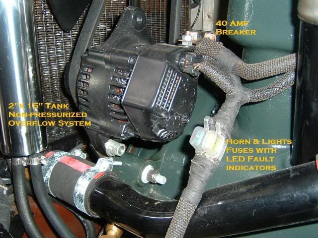
|
|
|
|
|
|
09-08-2010, 11:14 PM
|
#14 |
|
Senior Member
Join Date: May 2010
Location: Calgary, Alberta, Canada
Posts: 211
|
Steve and Mike - thanks for your discussion on this topic. It sounds like my wiring mods to try and set up an exciter circuit were for not and there is really nothing I can do at this point. Anyway - my alternator works well once it wakes up. I still like the look of the generator and plan to purchase a EVR for mine in the next while.
Thanks again. Mike H |
|
|
|
|
«
Previous Thread
|
Next Thread
»
 Linear Mode

|
|

| Sponsored Links (Register now to hide all advertisements) |
|
|
All times are GMT -5. The time now is 08:06 PM.