|
|||||||


| Sponsored Links (Register now to hide all advertisements) |
|
|
 |

|
Thread Tools | Display Modes |
 10-20-2011, 02:57 PM
|
#1 |
|
Senior Member
Join Date: Feb 2011
Location: NNNNNNNNJJJJJJJJJJ
Posts: 6,811
|
Can anyone send me a few photos of their cab being assembled? Particularly from the door stops back? (maybe a web page?)
I am roughing in the body on my frame- installed the cowl last night and doors. Need to know where the frame wood sits and if it is shimmed and where to make it level/even with the doors. my email is [email protected] would like to rough in the rear as soon as I know what to do. Thank you. |

|

|
|
10-20-2011, 04:21 PM
|
#2 |
|
Senior Member

Join Date: May 2010
Posts: 130
|
What year car? New wood or original wood? If new wood, then who made it? Did the car come in pieces or did you disassemble it? Do you have the four triangle pieces for the door posts? Have you looked at the Cabriolet club's Cabrioletter? There are some great articles in there on what exactly to do to adjust/trim your wood to fit along with plenty of measurements.
I am asking all these questions because everything (in my opinion), on a 68B, starts with fitting the door post wood to the correct height, angle, and twist. The cowl and doors are then adjusted to match the door post. Then the rear quarters are also adjusted to the door post. I can help you with a 68B, but I am useless if you have a 68C. |
|
|
|
| Sponsored Links (Register now to hide all advertisements) |
|
|
|
10-20-2011, 11:45 PM
|
#3 |
|
Senior Member
Join Date: Feb 2011
Location: NNNNNNNNJJJJJJJJJJ
Posts: 6,811
|
68B-original wood and no, I didn't pull it apart. Bought the body in pieces. I see 2 triangle pieces for the doorposts, but not 4.
I joined the cabriolet club, but never recd. anything beyond 1 set of papers that mentioned the articles. How do you recv the reg newsletters? my email is [email protected], if you might have a few photos to send? thank you for your help. |
|
|
|
|
10-21-2011, 01:01 AM
|
#4 |
|
Senior Member
Join Date: Aug 2011
Location: Millbrae, CA
Posts: 504
|
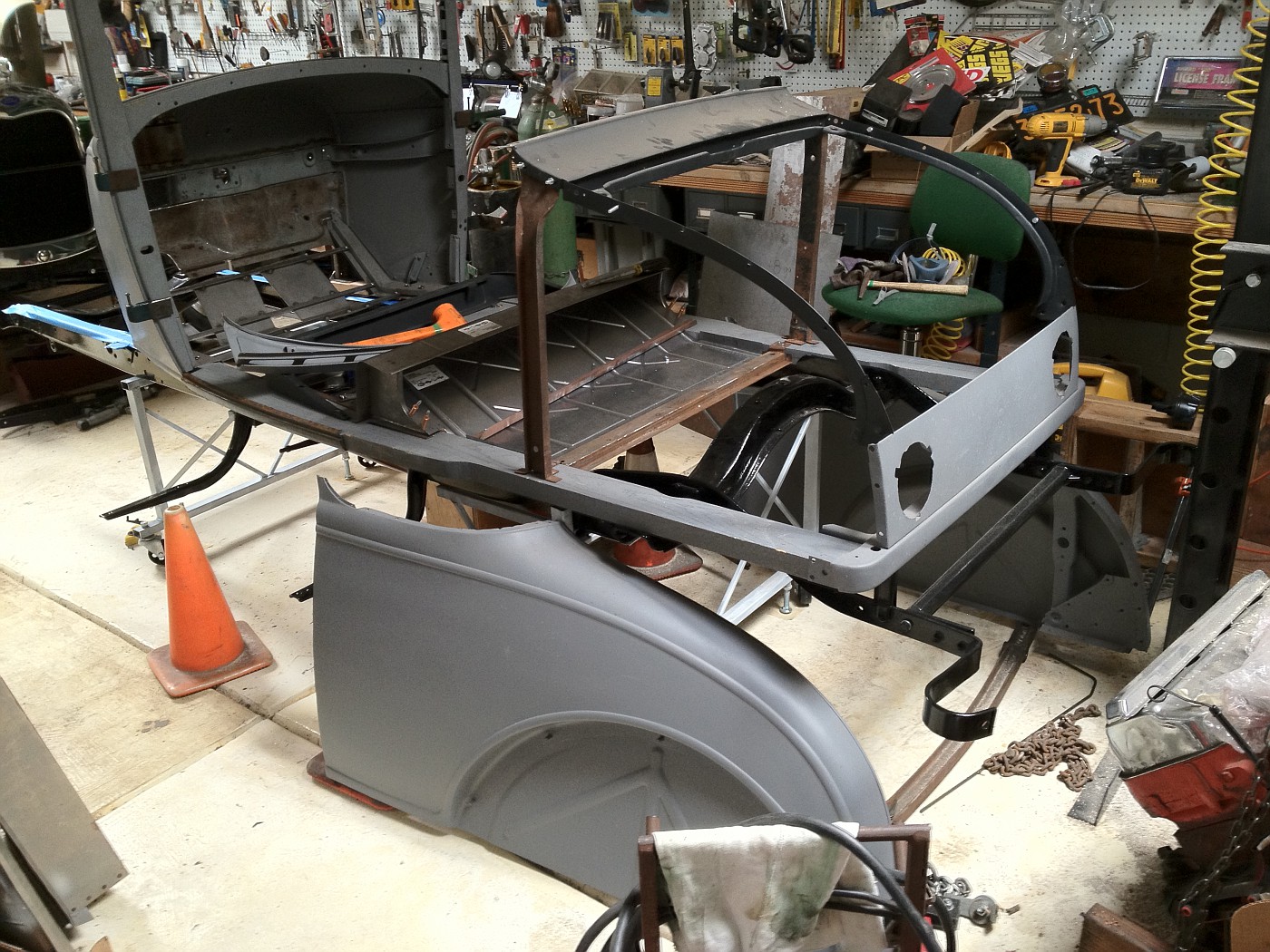
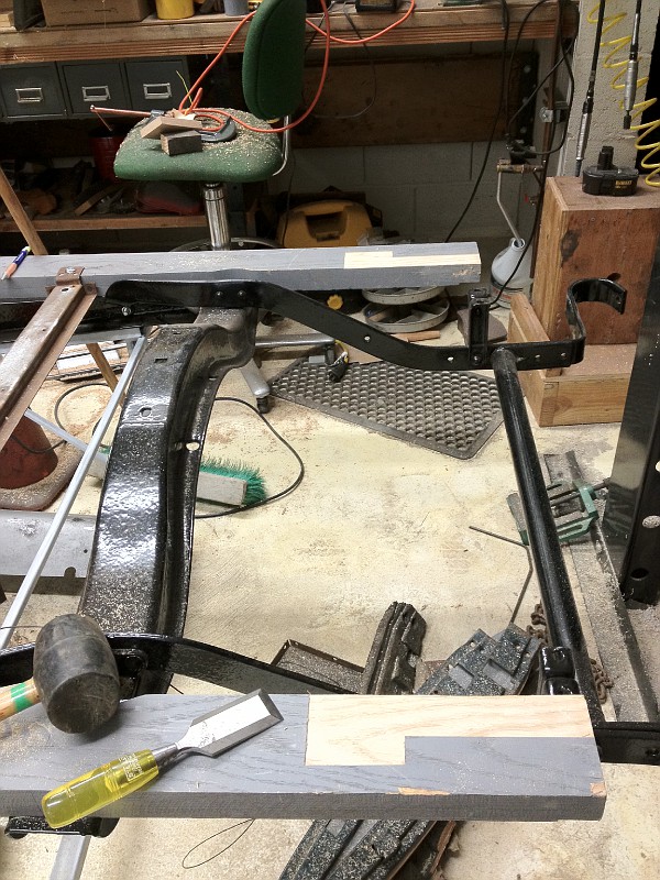
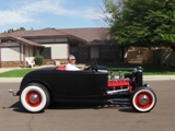
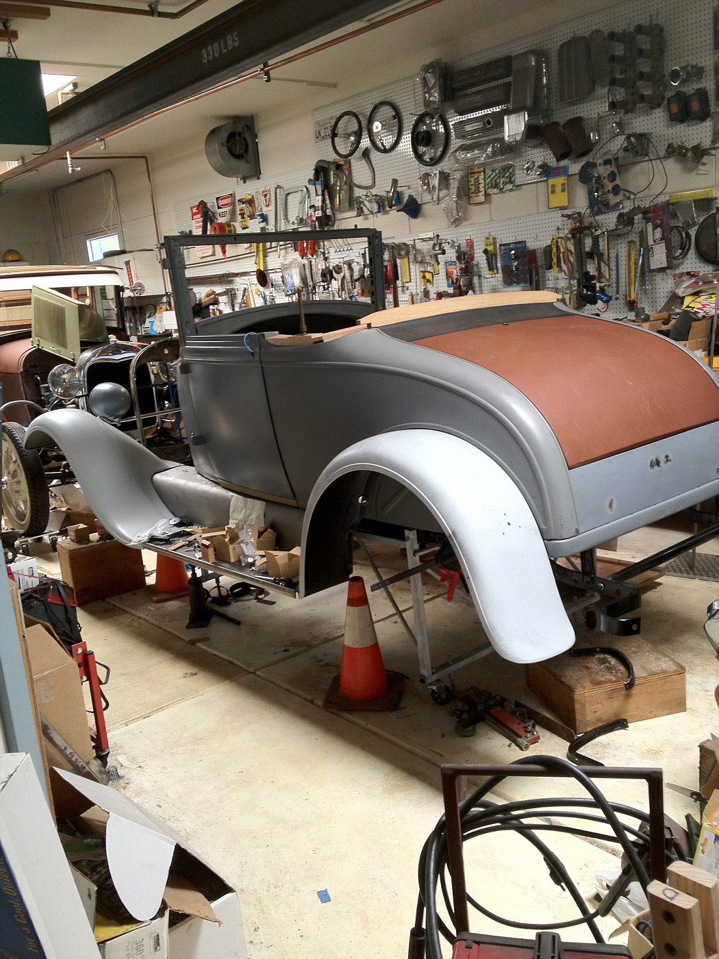
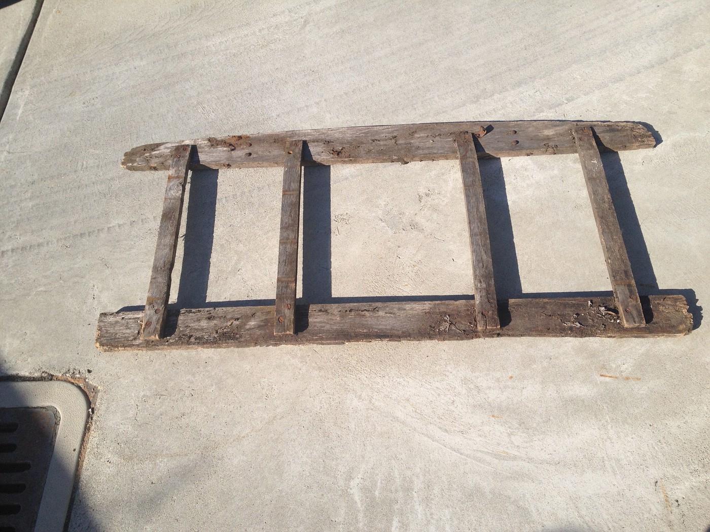
I just subscribed to this thread. I am about at this same point on my 68A and looking for guidance, too. The car was purchased new by my father in '29, but he gave it to his mother after only a couple years and I got it in '58. We replaced the rotted back half of the wood rails around '62, and did new top bows then....but the body was never fitted properly after my grandmother's many hard miles of northern CA driving in the '30s and '40s and much time out in the weather. Car and body were fully disassembled about 20 years ago (storage constraints), got a Cubel wood kit about 15 years ago. Finally retired, I am putting it back together. Frame is on a stand with leveling bolts.
Guess I have to start reviewing my Cabrioletter back issues. I just did not remember any particular issues with a lot of guidance on wood assembly. It is feeling like a challenge to not make irretrievable mistakes in cutting or drilling the replacement wood where it is not quite like the original, i.e., stepped cross braces, different widths from my rotted original wood. ...but having some original wood, even heavily rotted partial pieces is a help, and rusty 'swiss cheese' sheetmetal is useful too. ...wish I had more. Getting the B post properly located is my big worry. I foresee a lot of temporary assembly, measuring, fitting, testing, disassembly, etc. before ever cutting the notch for the B post. I hope this thread draws more comments, advice and photos. frame on stand, with rails on top, but not fitted to lay flat 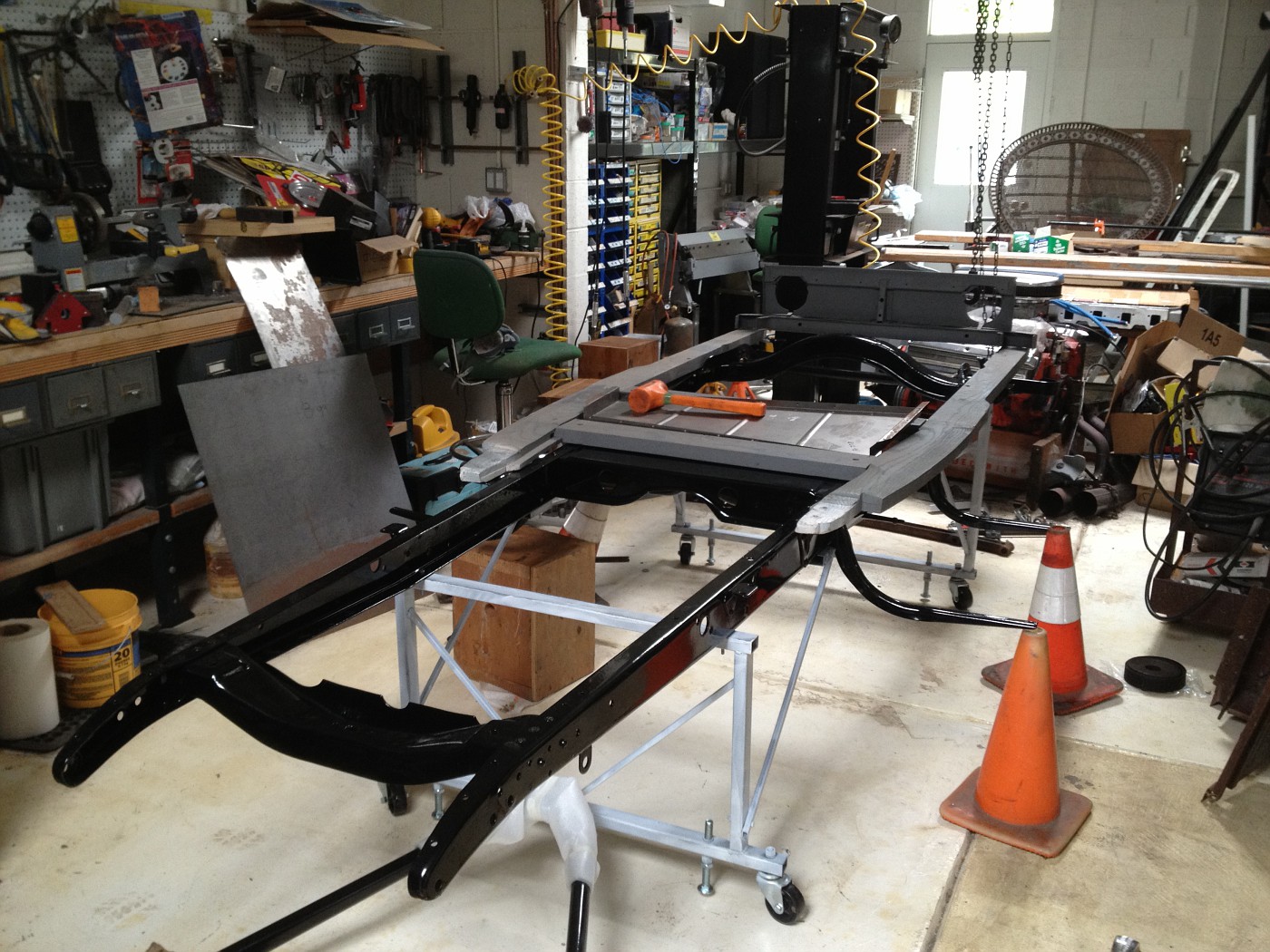
Last edited by Russ B; 10-21-2011 at 01:08 AM. Reason: add photo |
|
|
|
|
10-21-2011, 05:44 AM
|
#5 |
|
Senior Member
Join Date: May 2010
Location: South East NJ
Posts: 3,398
|
Good luck with cubel wood.
Larry, the owner of the cab club, had published a nice article in the newsletter many years ago. It was a multipart article that takes you through assembling a 68b from a pile. Unfortunately Larry refuses to participate online and would prefer to sell you an expensive complete set of back issues. So you might be able to find someone to scan in the article and email it. Calling Larry directly might be informative too. Learning how to search Bob cabriolet website is helpfull since many topics about the cabriolet have been covered already. |
|
|
|
|
10-21-2011, 05:54 AM
|
#6 |
|
Senior Member
Join Date: May 2010
Posts: 130
|
Sponsored Links (Register now to hide all advertisements)
Measure 26" from the back of the cowl to the front of the door post wood. The notch is 1 9/16 wide and 1 15/16 (or just 15/16?) deep, measure in from the bottom of the wood sill. Important, the notch will actually be further back than the 26" due to the shape of the door post. The Cabrioletters have a multi-part series that takes you through all the steps on fitting new wood and assembly. I will look later tonight for which letters you need to buy and the contact information. But, I would suggest buying all the back copies for 1 price. Ronn, if you haven't already looked, try this website: http://www.cabriolet.modelahouse.com/ Click on Cabriolet pictures or Picture Gallery. There are tons of pictures that may get you started. Having original wood is a great start, if it is in good condition and not warped out of shape. Also, there should be 4 triangle pieces with different part numbers for right and left side. Last edited by 30cabriolet; 10-21-2011 at 06:00 AM. |
|
|
|
|
10-21-2011, 07:17 PM
|
#7 |
|
Senior Member
Join Date: Aug 2011
Location: Millbrae, CA
Posts: 504
|
[QUOTE=30cabriolet;292704]"Getting the B post properly located is my big worry. I foresee a lot of temporary assembly, measuring, fitting, testing, disassembly, etc. before ever cutting the notch for the B post."
Measure 26" from the back of the cowl to the front of the door post wood. The notch is 1 9/16 wide and 1 15/16 (or just 15/16?) deep, measure in from the bottom of the wood sill. Important, the notch will actually be further back than the 26" due to the shape of the door post. The Cabrioletters have a multi-part series that takes you through all the steps on fitting new wood and assembly. I will look later tonight for which letters you need to buy and the contact information. But, I would suggest buying all the back copies for 1 Price. " Thanks. I found a reprint on the first article , about #112. I found my newsletters are scattered around. Will look for all. |
|
|
|
|
10-22-2011, 04:44 PM
|
#8 |
|
Senior Member
Join Date: Feb 2011
Location: NNNNNNNNJJJJJJJJJJ
Posts: 6,811
|
Russ, thank you for that photo. Looks like i am missing some wood. I guess I need some schematics of the basic framiing.
I did join the cabriolet club, but recd basically nothing and only a one time response. Don't even get the point of the club.... |
|
|
|
|
10-25-2011, 12:28 AM
|
#9 |
|
Senior Member
Join Date: Aug 2011
Location: Millbrae, CA
Posts: 504
|
I do not know how typical this is, but my replacement wood does not appear to be at all the same width (front to back) as my original front cross piece.
 For reference, I placed the Briggs Body tag on the old front cross piece over the nail holes from where I removed it. ...however, the new sheet metal seat floor pan, under the seat, and the second cross piece seem to fit together properly with the new front piece. ...and the new floor pan is the same size as my old one. 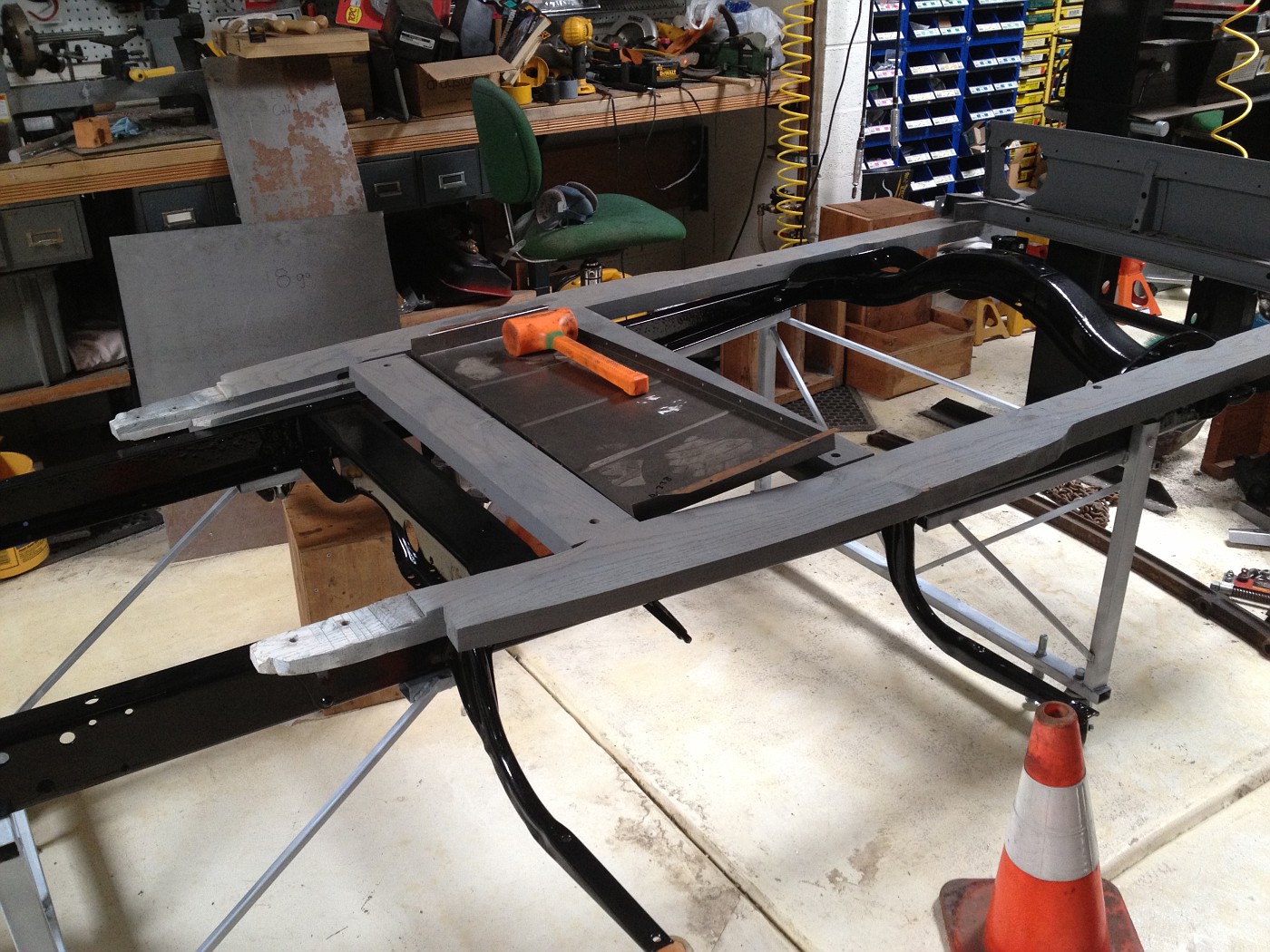 Note that my original piece has an angle iron support for the floorboard. The new piece besides being wider has a lip of wood at the back where the front of the seat floor plan will have to attach. I guess it is possible that my original front cross piece was made of two pieces of wood glued together and the back half fell off. I'll have to look for nail holes to match the floor pan. (in the next photo) The left side of my front cross piece is laid in position on top of the new wood. The bottom edge of the old wood is where the back of the floorboard will sit, and matches the edge of the new wood. 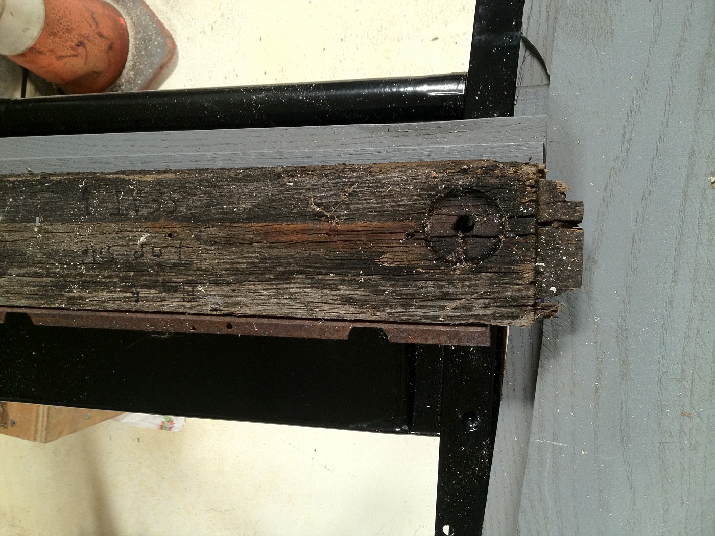 My plan is to move the angle iron from the old to the new piece. Any comments that might shed some light? I do not think the new front piece is placed backwards, is it? As I have the front cross piece now placed, the standard floor board seems like it would fit properly. I am still not cutting any wood yet, until I am absolutely sure of what I am doing. ...and a Ford Barn housekeeping question, as a new person here I am not sure whether i should be posting this on the original poster's thread or if I should be starting a new one. But for now I am posting here as we are both interested in the same topic. Please let me know if I am out of line. |
|
|
|
|
10-25-2011, 01:07 AM
|
#10 | |
|
Senior Member

Join Date: May 2010
Location: South Florida
Posts: 14,054
 |
Quote:
While your answers are not specific to the door stops, he does ask about assembly photos and you do have photos and questions that would be common to the person building the cabby. I don't see any problem.
__________________
What's right about America is that although we have a mess of problems, we have great capacity - intellect and resources - to do some thing about them. - Henry Ford II |
|
|
|
|

|
10-25-2011, 04:55 AM
|
#11 |
|
Senior Member
Join Date: May 2010
Posts: 130
|
Russ,
Looking at the photos above I can see between your wood and the frame rail. Is your wood sill sitting flat on the frame? If it is rocking on the rivets at the rear crossmember, you can countersink the spot where the rivets interfere with the wood allowing the sills to sit flat. If they still do not sit flat, then you need to check your frame for a bend. As for your other questions, I will PM you as this is gonna take some phone time to share info. |
|
|
|
|
10-25-2011, 05:31 AM
|
#12 |
|
Senior Member
Join Date: May 2010
Posts: 130
|
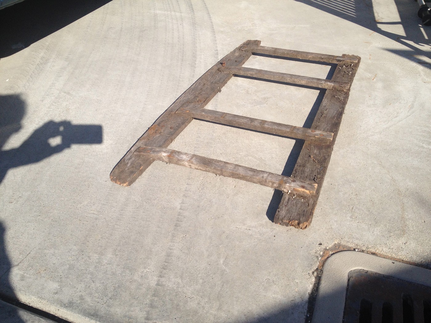
Found some old photos on my computer here at work. The second picture showing the rear of the wood is before I notched the wood as required to fit the quarter panels.
|
|
|
|
|
10-25-2011, 06:35 AM
|
#13 |
|
Senior Member
Join Date: May 2010
Posts: 130
|
And another thought, the wood for a fixed seat Cabriolet may be different than the wood for an adjustable seat car. I think, but I don't know, that the difference is in the #1 cross sill. You may have the wrong wood.
|
|
|
|
|
10-25-2011, 10:22 PM
|
#14 | |
|
Senior Member
Join Date: Aug 2011
Location: Millbrae, CA
Posts: 504
|
Quote:
I made some progress and stated fitting the under seat floor pan. 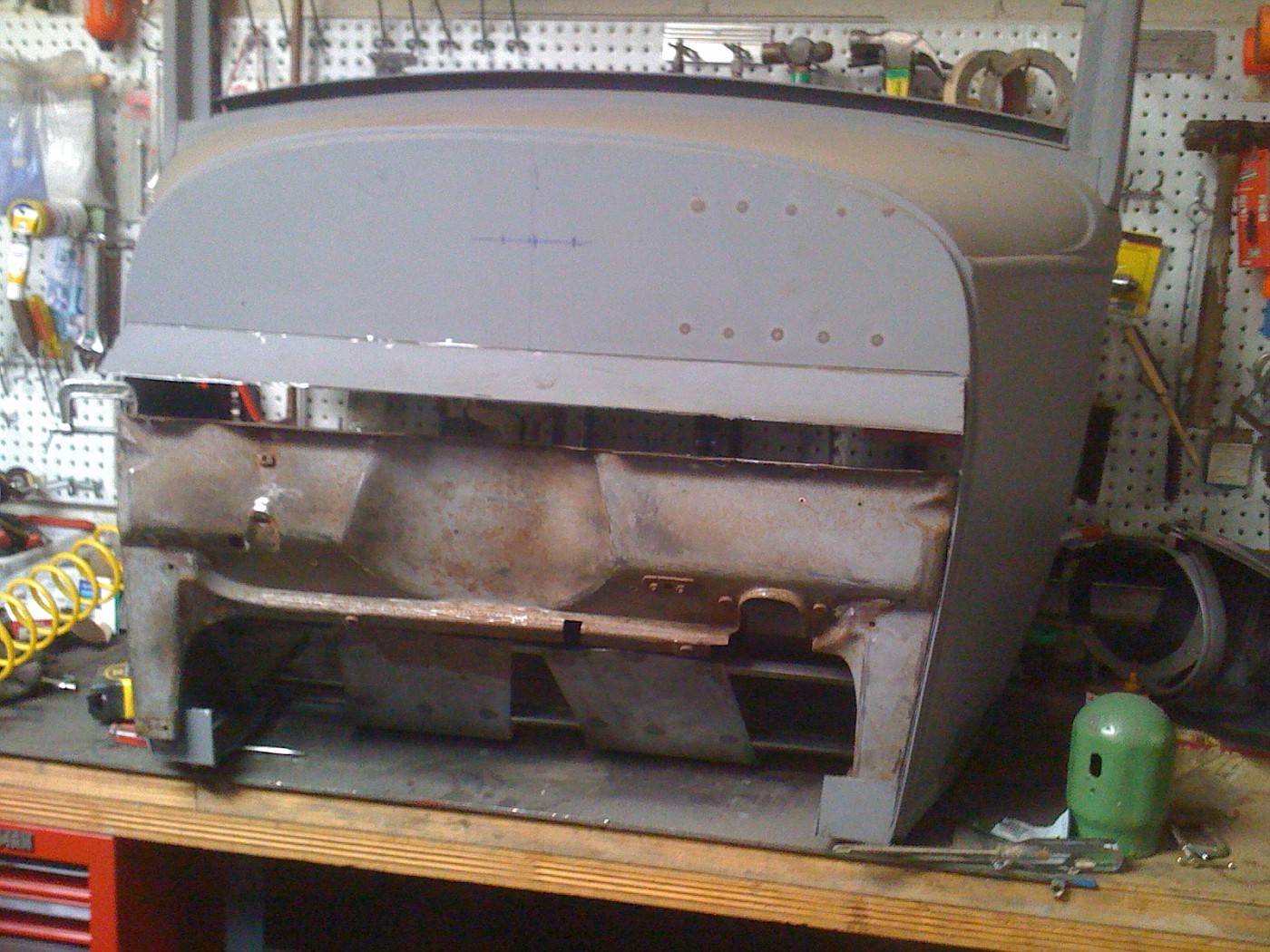 My original sheet metal pan mounted 5/8" further toward the front originally; but with the wood I have it is where it is, and the location does not impair fitting of anything else. I am thinking that perhaps Ford/Briggs made body wood design changes somewhat continuously as they did on many other parts of the car. If correct, that could mean my Cubel body wood kit represents a different point in time from when my car was built. The motor/frame number indicates an Aug 1, 1929 date. |
|
|
|
|
|
11-04-2011, 09:54 PM
|
#15 |
|
Senior Member
Join Date: Aug 2011
Location: Millbrae, CA
Posts: 504
|
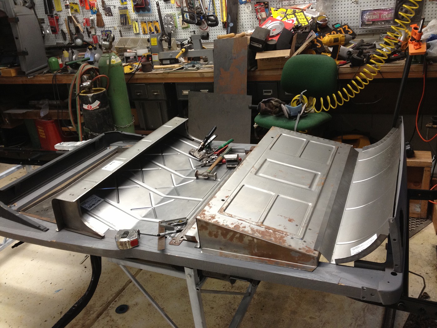
I am adding a photo showing the sheet metal that fits atop the wood sill rails of my '29.
 The metal is preliminarily fit only. It is new metal from MACs and as is typical, it needs work. The front seat bottom riser is original as is the metal cross sill. The little pile of sheet metal bits are mostly from the angle pan fitting, using my original swiss cheese piece as a guide. The most work is needed on the front seat back riser at this point. The side pieces need to be pie cut about 3/8" at the back and welded back together so that the angle pan can be fully fitted. My plan is to fully fit the sheet metal (seat back riser, angle pan, metal cross sill, rumble seat pan, and curved back piece), then temporarily pop rivet it together and in place before fitting the B pillar and rear quarters and rumble seat/deck lid. After the body is fitted, I would disassemble the upper sheet metal, remove the pop rivets, install the 3/16" waffle-bucked rivets, fully screw/nail in the floor pan sheet metal to the wood sills and paint that as an assembly. The remaining upper (body) sheet metal can be painted in separate pieces and then assembled, touching up any nuts/bolts scarred during assembly. Is that a reasonable approach? I also have a question about the metal cross sill. I sort of recall reading that it should be marked with assembly plant and possibly body assembly date information. I see no markings on the top side, is it marked on the bottom? I am guessing it should indicate a July 1929, mol, assembly in San Francisco, but so far I have found nothing. Where should I look? |
|
|
|
|
11-04-2011, 11:04 PM
|
#16 |
|
Senior Member

Join Date: May 2010
Location: Connecticut
Posts: 220
|
Great progress on your Cabriolet. I'm putting together an early '30 with a fixed front seat. I have yet to buy the sheet metal for the floor although I do have the under seat panel fitted. The first thing that came to mind was for you to pick up some Clecko fasteners instead of using pop rivets. They fit very tight and can easily be removed with special pliers. No drilling and enlarging the holes. Small screws could be used but don't come apart as fast as Clecko's. I'll have to double check and see if they fit the holes in my cross sill.
I was hoping the seat back riser would have been "fit and play" but it sounds like that may not be the case. A friend of mine with a mid-30 Cabriolet in the next town over has his seats out so I'll have to pick up the riser soon and compare it to his. I was fortunate to find a nice cross sill channel at Hershey this year. A quick check of the channel revealed no date or other markings. Cheers Rich
__________________
E30 68-B Cabriolet
|
|
|
|
|
11-05-2011, 12:39 PM
|
#17 | |
|
Senior Member
Join Date: Aug 2011
Location: Millbrae, CA
Posts: 504
|
Quote:
|
|
|
|
|
|
11-07-2011, 10:07 PM
|
#18 |
|
Senior Member
Join Date: Aug 2011
Location: Millbrae, CA
Posts: 504
|
The unmodified reproduction sheet metal front seat back riser, front straight up, tails too long:
 The reproduction metal is just sort-of close to start with. The riser is still 1/4" short after the modifications and 21 ga, but the overall shape is much closer to original, looks a lot more like the original does, and fits much better to the angle pan and sills. It would not be usable if a serious restoration were being attempted. after modification, angled back a bit and tails cut to proper length:  markup of piece showing changes needed: 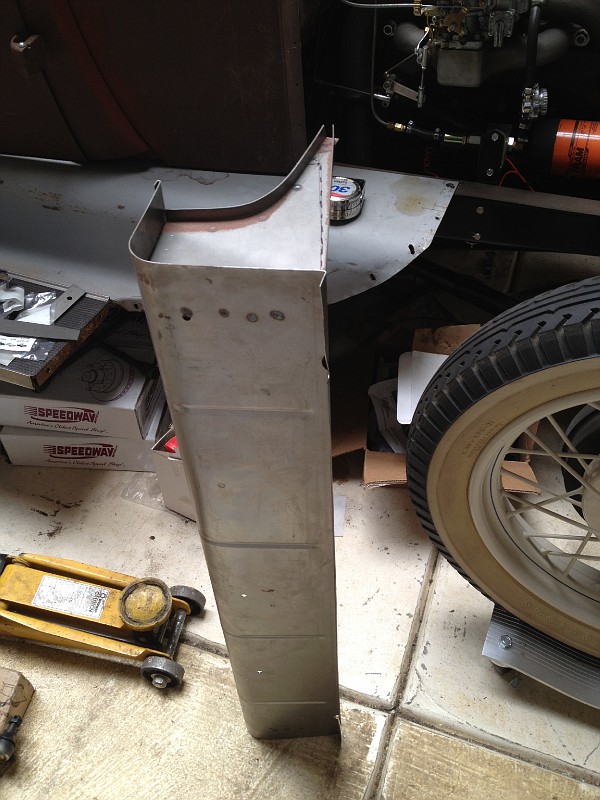 The lower flange was flattened, the excess metal was cut, and the lower flange was bent up on the dotted line. corrected side piece 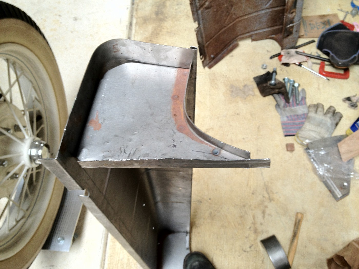
|
|
|
|
|
11-07-2011, 10:29 PM
|
#19 |
|
Senior Member
Join Date: Feb 2011
Location: NNNNNNNNJJJJJJJJJJ
Posts: 6,811
|
Russ, thank you for the photos!
A real big help. I didn't know there was a fixed seat and adjustable seat. Am thinking mine is adjustable. Looks like I am missing a piece or two also. |
|
|
|
|
11-08-2011, 12:42 AM
|
#20 | |
|
Senior Member
Join Date: Aug 2011
Location: Millbrae, CA
Posts: 504
|
Quote:
I guess the 68B had the adjustable seat option. I would think that would affect the package tray area as well. ...and maybe the triangle top pieces (turnbuckle brace), too?? You might take a few pics and post some to show all the parts that you have, and someone will likely be able to say what is missing. I am just slowly progressing on mine, and if you don't mind, I would plan to keep posting pics here on your thread of the body as it goes together. Getting the feedback from the folks who have already done it does help on getting it right. Russ |
|
|
|
|
|
11-08-2011, 07:29 AM
|
#21 |
|
Senior Member
Join Date: May 2010
Location: Connecticut
Posts: 220
|
This picture of an original 68-B fixed seat front seat riser was taken by my dad in the late 70's when he was restoring his Cabriolet. He tended to save everything but I can't find the remains of the original today. The riser to the left is one he made from scratch and may very well have the correct angles for the end pieces transposed from the original.

__________________
E30 68-B Cabriolet
|
|
|
|
|
11-10-2011, 09:00 PM
|
#22 |
|
Senior Member
Join Date: Aug 2011
Location: Millbrae, CA
Posts: 504
|
making progress but time to fill a couple big tail light holes in the back panel before I go any further
 With the cowl in place, I am looking at the alignment of the bottom reveal with the door bottom sheet metal, original and new. 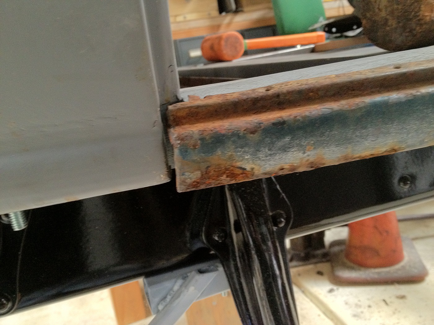 cowl reveal looks a bit short 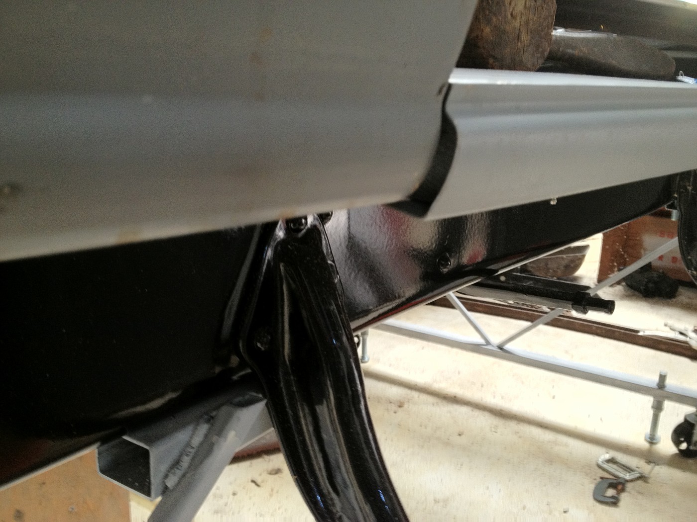 compared to new metal it still looks short; but the new metal shape is looking too angular at the bottom. My cowl bottoms were patched many years ago and they appear to be about 1/8 to 3/16" too thin a reveal at the bottom rear. The front is original sheet metal. While I am not doing a "points" restoration I want to do as good as I can within limits of my abilities. My question is: how perfect were fits on original Briggs bodies? I am planning to rework both the cowl bottom and the shaped pieces under the doors, but do not know how perfect I should try to get them. |
|
|
|
| Sponsored Links (Register now to hide all advertisements) |
|
|
|
11-10-2011, 09:29 PM
|
#23 |
|
Senior Member
Join Date: May 2010
Location: Connecticut
Posts: 220
|
A friend of mine has a 68-B and this his how his drivers side bead below the door meets the cowl. The outside of the bead lines up somewhat with the cowl bead and the back edge of the bead lines up with the cowl recess for the door.

__________________
E30 68-B Cabriolet
|
|
|
|
|
12-07-2011, 12:33 AM
|
#24 |
|
Senior Member
Join Date: Aug 2011
Location: Millbrae, CA
Posts: 504
|
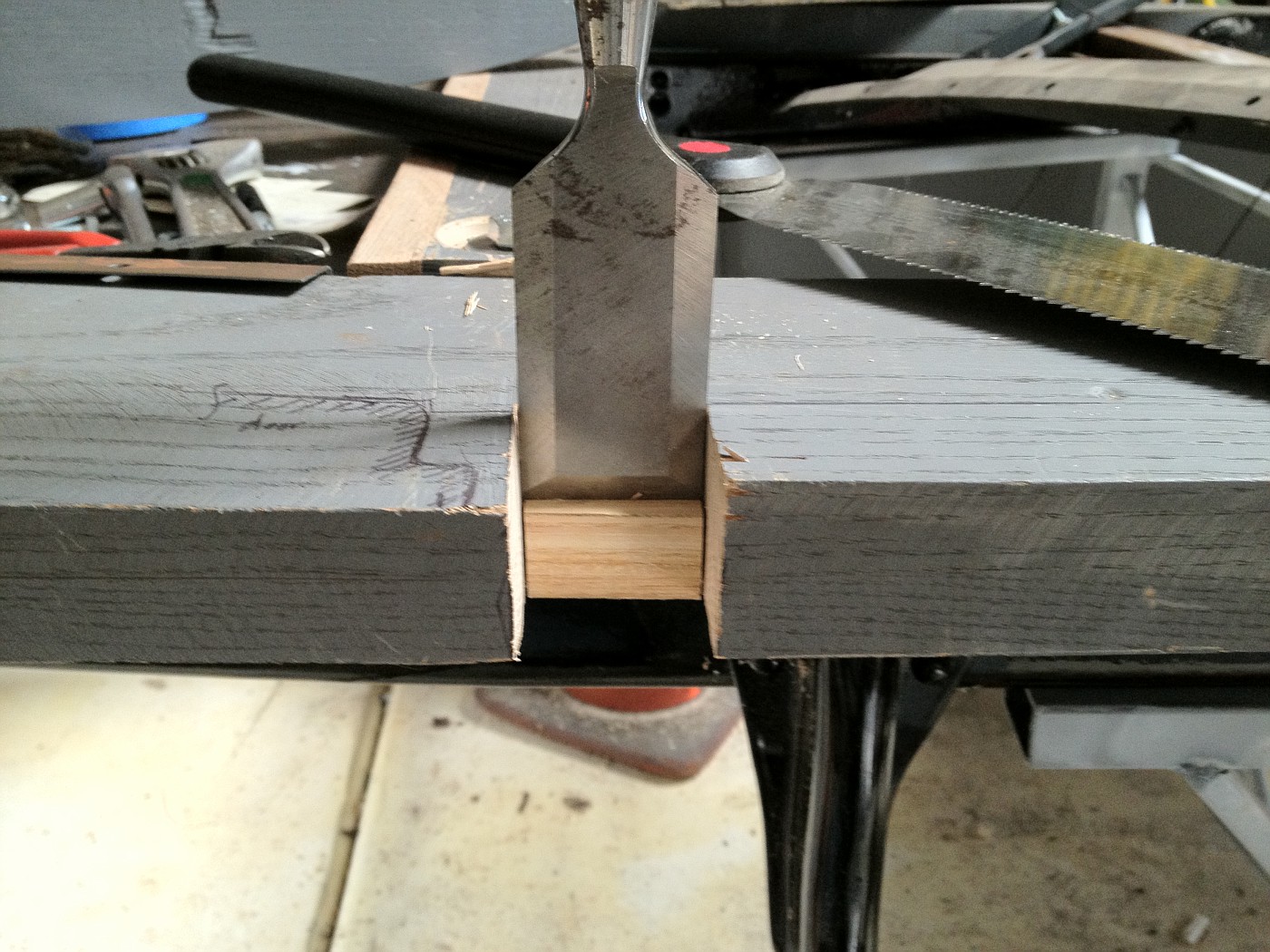 I cut in the B pillar a few days ago. I marked the door edge profile on the sill to confirm the proper location. |
|
|
|
|
12-07-2011, 07:47 AM
|
#25 |
|
Senior Member
Join Date: May 2010
Location: South East NJ
Posts: 3,398
|
I see the rumble seat pan you have the front corners cut and bent up to clear the wood.
Are you aware that they were just cut out? When I get a chance I will look for my pictures of what the corners look like off an original. I hope you guys realize a lot of pictures already exist over on Bob's cabriolet website. Though these are some nice pictures for people working with the repro parts. |
|
|
|
|
12-07-2011, 04:40 PM
|
#26 |
|
Senior Member
Join Date: Aug 2011
Location: Millbrae, CA
Posts: 504
|
Sponsored Links (Register now to hide all advertisements)
I knew I was not done with the corner, so I did not cut and toss, not knowing how to do it right. I generally go slow enough to not make irretrievable errors. I have spent time looking at Bob's cabriolet website, but there are so many photos there and the site's organization is not suited for quickly finding the info I am looking for. I just need to spend a lot of time looking through a lot of info each time I go there. It is nevertheless a great resource. I know it will be very helpful when I get to doing the upholstery. I will look some more for a photo of the corner detail. I am guessing it is the same as the edge of the rumble seat floor pan as it dips down between the sill rails just behind the front seat riser. My B pillars need to be shaved in the middle outside to properly match the outside curvature of the doors. ...about 1/16" max. That needs to be done before I route a vertical notch (about 1/4" by 3/8") in the outside front corner of the pillar to let the front edge of the sheet metal quarter panels sit properly. I have a Bosch planer that is marked in 1/64" increments, but I have not used it to shave curved surfaces before. ...a little experimentation is needed; but first I need to acurately measure and mark the pillars for planing. Using reproduction sheet metal is a challenge as it is generally of such poor quality in not always obvious ways. I am relatively lucky having good original sheet metal for almost all but the floor and rumble seat areas. |
|
|
|
|
01-04-2012, 12:39 AM
|
#27 |
|
Senior Member
Join Date: Aug 2011
Location: Millbrae, CA
Posts: 504
|
Finally today, I routed the "L" shapes at the back of my main sills
 I just followed the guidance in The Cabrioletter (#114). The article suggested cutting 'about' 1/16" deep, but I cut a little less. The bases of the two pieces that fit on top of the "L" recess are only 0.035" thick, so I went about 0.040-0.45." I have been fitting new wood for the doors, too. 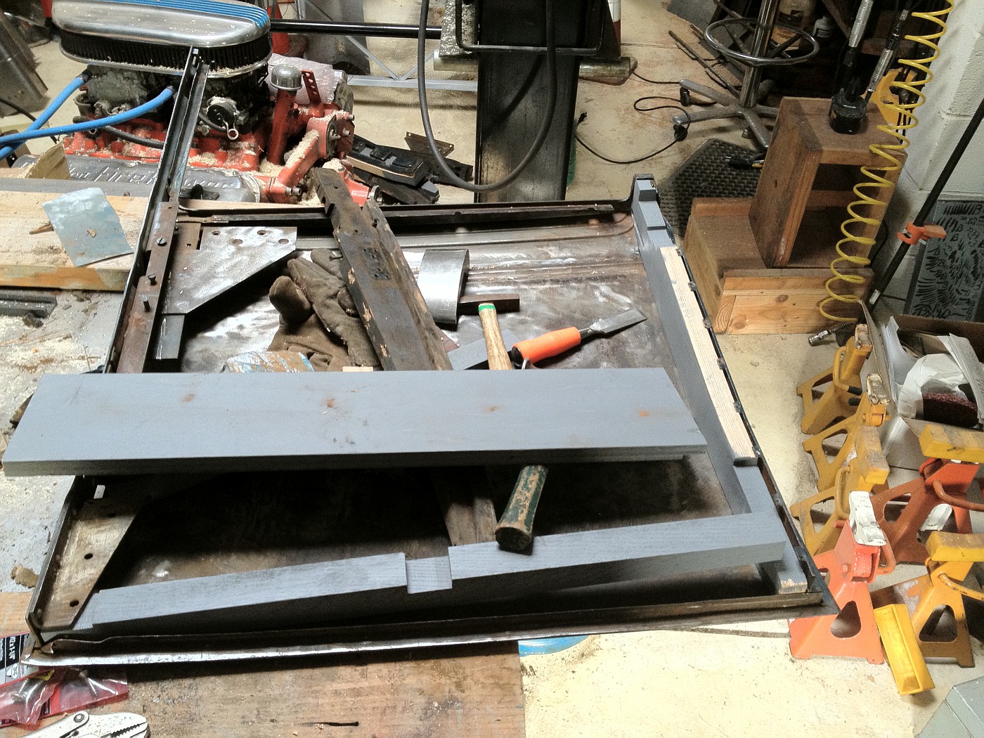 Some of the wood pieces had to be completely re-cut, and others additional thickness had to be added, but most only required a little shaving and the normally expected fitting effort. 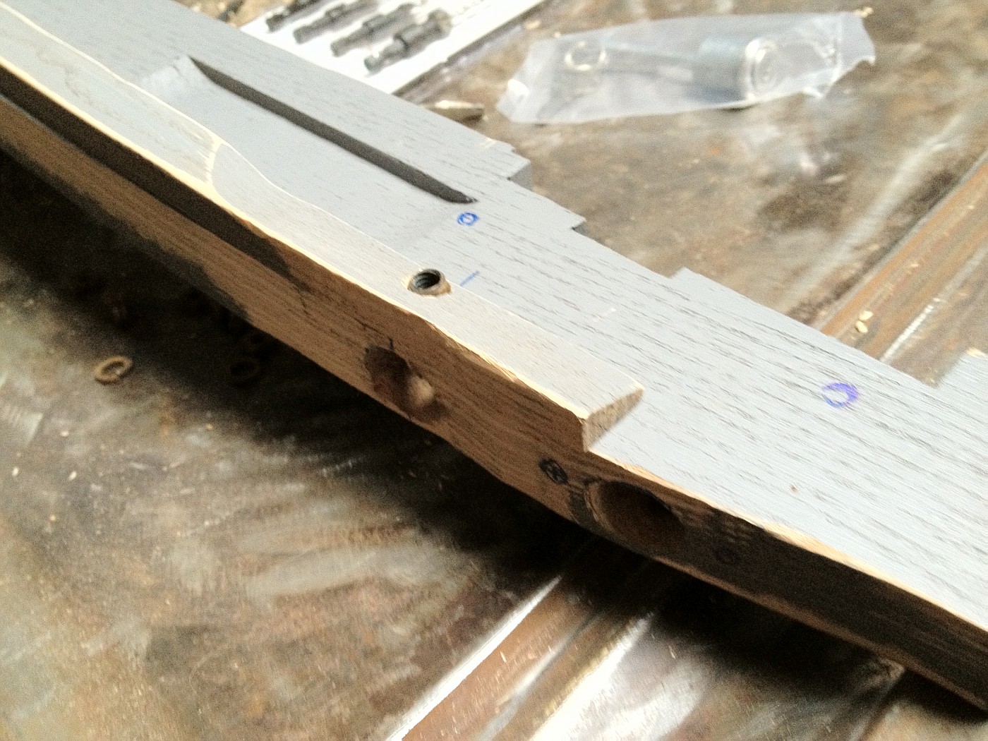 This is the two rear door wood pieces and the photo shows the right door lock hole and with the set screw holder in position, threaded through the two pieces. The piece that fits at the top of the door needed extra work. 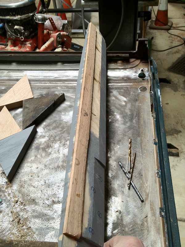 The reproduction piece was nearly 3/16" too thin at its top edge. The unpainted strip was thinned down to proper thickness and glued onto the reproduction piece. The resulting piece looks a bit oddball, but has all needed mating surfaces and will not be seen after door is assembled. As the sheet metal on these Briggs Body doors was originally skinned on top of a wood and metal frame, replacement of just the wood can not be done in the same manner as the door was originally constructed. This top piece is the most difficult to place back into the metal framework. The Cabrioletter suggested using a two piece top piece; but with a little modification, I think it can be installed as a single piece and be stronger than a two piece one would be. I will await final assembly of the door wood until after the door skins have been sand blasted and primed. The sheet metal is amazingly good on these doors. The only patch needed was from a tear/crumpling coming back from the door handle, only about one square inch of metal! 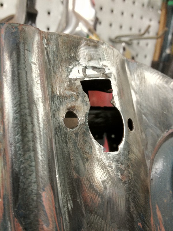
Last edited by Russ B; 01-11-2012 at 02:23 PM. Reason: Correct reference cited |
|
|
|
|
01-25-2012, 10:28 PM
|
#28 |
|
Senior Member
Join Date: Aug 2011
Location: Millbrae, CA
Posts: 504
|
Just adding a few more photos to the thread.
 This shows some of the inside back braces, everything still loose at this time. 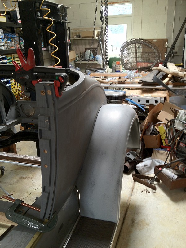 Before I tie anything down, I want to assemble as much as possible to see if there are any obvious fit problems. 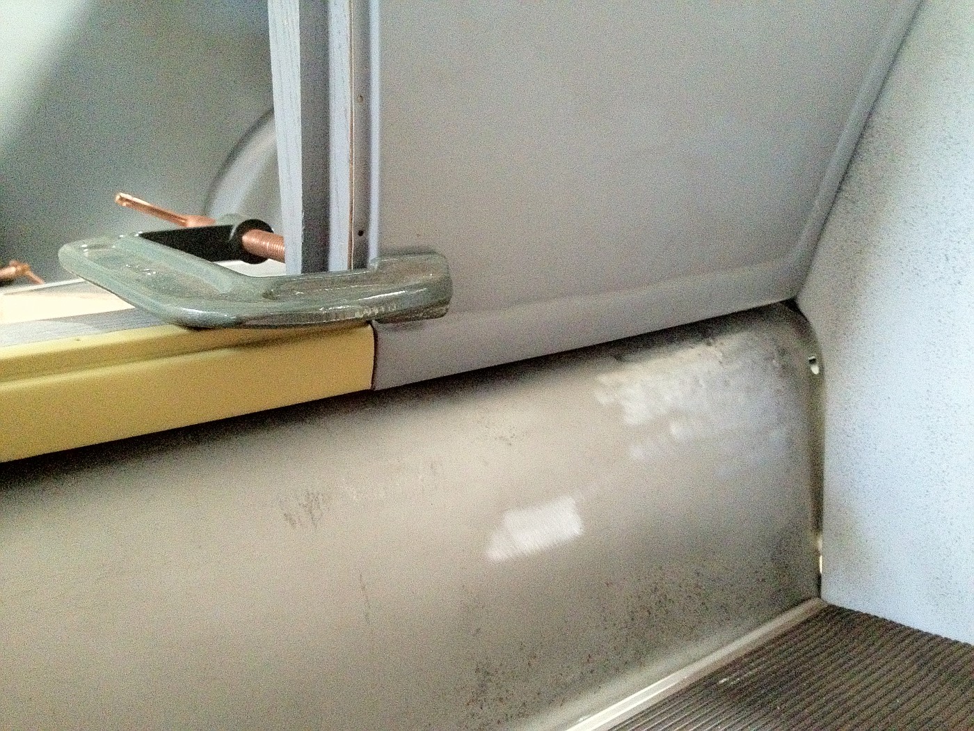 I had to cut an 1/8" off the bottom of my B pillar to get these pieces to line up. 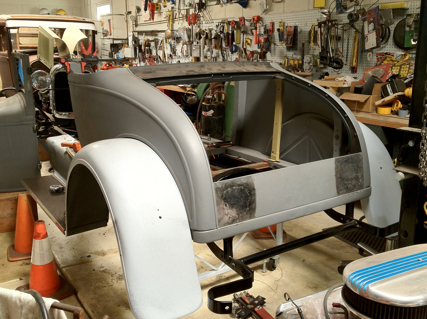 Still a lot of work to make it all fit. As I am using a reproduction rumble/trunk lid, I will try to fit it on soon to see what more needs to be done to get a matching curvature on the back panel. |
|
|
|
|
01-27-2012, 05:41 PM
|
#29 |
|
Senior Member
Join Date: Feb 2011
Location: NNNNNNNNJJJJJJJJJJ
Posts: 6,811
|
Well fellas, was just out in the garage (in the 60's today!) and got the sills on and everything went together like a jigsaw puzzle! Will need help lifting and readjusting the cowl and lifting the back body on, but everything is lining up. The photos you guys sent in were a tremendous help....
I am missing a cross brace or two, but otherwise coming together nice. My seat is adjustable, btw. Wish I knew how to readily upload photos.... |
|
|
|
|
01-27-2012, 08:52 PM
|
#30 | |
|
Senior Member
Join Date: Aug 2011
Location: Millbrae, CA
Posts: 504
|
Quote:
That cowl is heavy. I have been able to move mine short distances by myself, mostly it is stripped, no gas tank, etc. ...but it generally takes a bit of recovery time afterward for my own old body. The body is being built on the frame, which is on a stand. It still will be a challenge when I am ready to go to full assembly. ...and then to paint and reassembly. Photos are not hard to do if you have a photo storage site on line like Fotki.com. I just post from there to here. Last edited by Russ B; 01-27-2012 at 09:48 PM. Reason: Typo |
|
|
|
|
|
01-27-2012, 08:59 PM
|
#31 |
|
Senior Member
Join Date: May 2010
Location: South East NJ
Posts: 3,398
|
From experience,
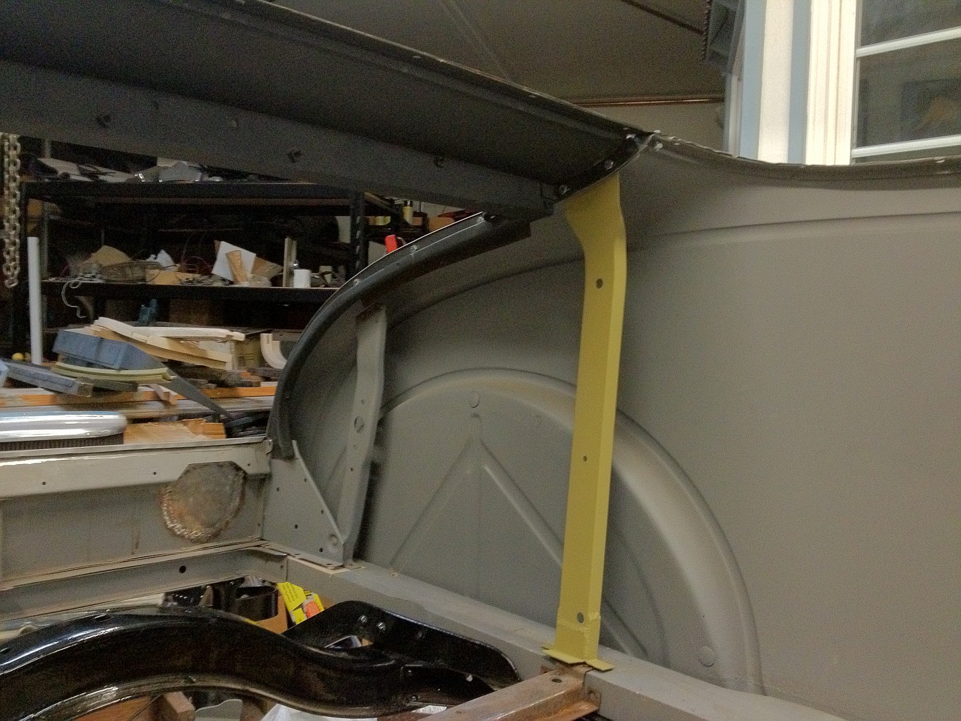
Since you had to remake the bottoms of the forward braces that go from the sill to the upper cross piece (the yellow ones in your pictures) you may find the doors do not line up top to bottom. I found I could pry these braces up some to get the doors to line up top to bottom. In other words, if it looks like the qtrs are too wide or narrow at the top, then you need to adjust these brackets. I had to make my brackets up from repros and I had to guess at the proper length. That coupled with having to do extensive work on the qtrs. I was shy by a couple of pieces of 18 gauge sheet metal under the braces of getting the doors to fit. |
|
|
|
|
01-27-2012, 10:09 PM
|
#32 | |
|
Senior Member
Join Date: Aug 2011
Location: Millbrae, CA
Posts: 504
|
Quote:
|
|
|
|
|
|
01-27-2012, 11:10 PM
|
#33 |
|
Senior Member
Join Date: May 2010
Posts: 332
|
You are not ready for this yet but be sure to fit the windows and slides to the doors before you think it is ready for final paint. Don't ask why I know.
|
|
|
|
|
01-28-2012, 07:11 AM
|
#34 |
|
Senior Member
Join Date: May 2010
Location: Connecticut
Posts: 220
|
Russ
I've read that article in the Cabrioletter regarding the the "L" shaped recess in the rear of the chassis wood. After putting the rear half of the car together where the original rear brackets are mostly intact, my initial impression is the recess is not needed. I could be wrong but for now I can't see why it is needed as my brackets fit nicely on top of the wood without it. The series including issue #114 in the Cabrioletter has great information for fitting wood in these cars. One area that needs correction and I hope to get an article written this year is the fitting of the set screw for the passenger door lock. It is a small detail but the Cabrioletter in past articles has it wrong. The set screw housing should be inserted through the hole for the door handle and not from the other end. This is how it was done originally and makes for the strongest mount as the set screw housing boss presses against the larger door latch post. I'll post a picture later. Rich
__________________
E30 68-B Cabriolet
|
|
|
|
|
01-28-2012, 07:29 AM
|
#35 |
|
BANNED
Join Date: May 2010
Location: Walla Walla, Washington USA
Posts: 6,066
|
This is a great and interesting thread.
Nice work! Pluck |
|
|
|
|
01-28-2012, 08:02 AM
|
#36 |
|
Senior Member
Join Date: May 2010
Location: Naperville, IL
Posts: 1,387
|
Keep the pictures and dialog coming! I am saving them all for reference to use as I restore the body of my August '29 68A. The chassis is done. Thanks for making the effort. Gar Williams
Last edited by Aerocraft; 01-28-2012 at 08:05 AM. Reason: add photo |
|
|
|
|
01-28-2012, 11:26 AM
|
#37 |
|
Senior Member
Join Date: Jul 2010
Location: Oslo, Norway
Posts: 522
|
Russ, great post ! My cabriolet is a 1930, but I think a lot of the parts are identical, so I am also following your good work with great interest all the way over here in Norway !
|
|
|
|
|
01-28-2012, 03:09 PM
|
#38 | |
|
Senior Member
Join Date: Aug 2011
Location: Millbrae, CA
Posts: 504
|
Quote:
I did make the "L" recess and am still waiting to see if it is needed. I am not far enough along on my fitting to be sure. Briggs factory photos, in the "How To ..." series article on the 68C body show the "L" recess/notch, iirc. I think there is a good chance I will need it in my assembly. My fitting of door wood varied a bit from the Cabrioletter guidance as well. That wonderful guidance is a kind of bible for many of us doing this work, but I think all of us find slight differences or improvements in how we do the assembly. Once done with mine I plan to write something up and send it to Larry for use in the Cabrioletter as additional hints on assembly of the body. One additional thought, soon I will be tieing down my "B" pillars and have some uncertainty about the lower triangle pieces that fit behind them. The guidance in the Cabrioletter has two photos showing the open side of the lower piece facing toward the inside of the body while the upper triangle (turnbuckle) piece has the open side facing toward the outside of the body, #116, see figures "E", "F", and "G". When I disassembled my body many years ago, I scratched an "L" and "R" on my lower pieces indicating the open sides would face to the outside, like the upper pieces do. This seems logical for how I would envision factory, jig based, assembly of the body, they seem to fit properly that way, and that is how I am planning to do mine at this time. However, I think I have seen assembly photos on "Bob's Cabriolet Page(?)" indicating assembly with the top piece open side out and the bottom piece with the open side faced inward. Is one way right and the other way wrong? Thanks again to Ronn for starting this thread. |
|
|
|
|
|
01-29-2012, 08:15 AM
|
#39 |
|
Senior Member
Join Date: May 2010
Posts: 130
|
Russ,
The lower triangle pieces face towards the inside of the car and the uppers face towards the outside. If you look and the lowers you will see that the ends are bent to less than 90 degrees to allow the pieces to fit properly against the sills. There is a left and right side piece; they are not the same. The tops have to face towards the outside to allow for the triple hinge screws to fit correctly. Since I just finished assembly my car (just lacking a top), here is the most important tip I can give you about the B post. Leave the triangle brackets loose! Put one screw on each side and leave it until final assembly. The reason is that there is a lot adjustment to be found in the post when you are setting the door gap, but if you have it all screwed down tight, you will pretty much be stuck wherever you initially set it. As for the "L" shape cutout, I put in the cutout and am glad I did. The cutout allows you to raise or lower the back of the body just enough to affect the door gap. I ended up having to shim the triangle piece at the front of the L while the back was just fine. Better to cut it in and not need it then to need it and have to take the car apart to cut it in. |
|
|
|
|
02-18-2012, 11:56 PM
|
#40 |
|
Senior Member
Join Date: Aug 2011
Location: Millbrae, CA
Posts: 504
|
A few more cabriolet assembly photos that may be of help to someone.
The right side quarter panel still a little low compared to the B pillar and the turnbuckle brace behind it. 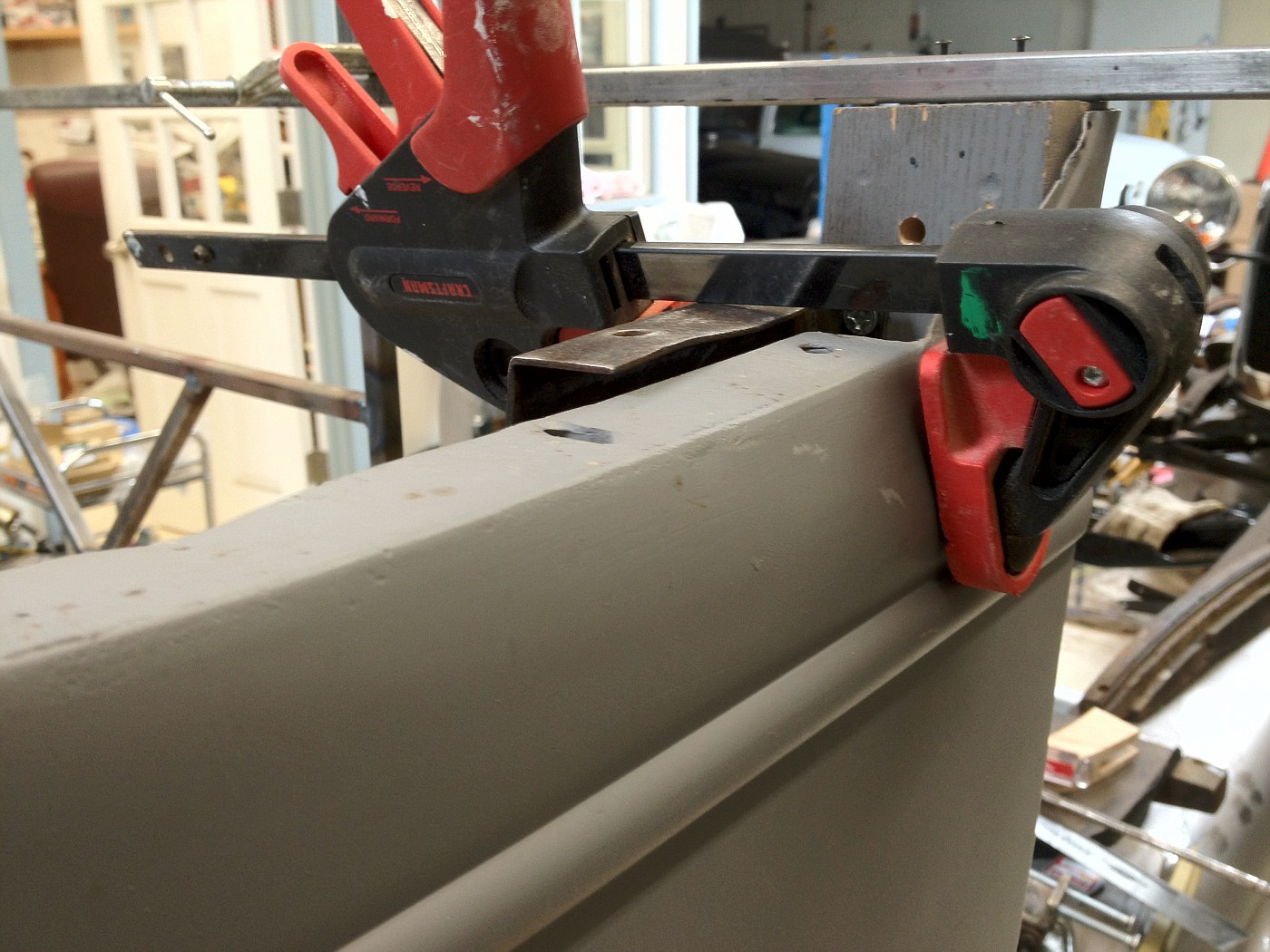 The same as above but looking from the inside. 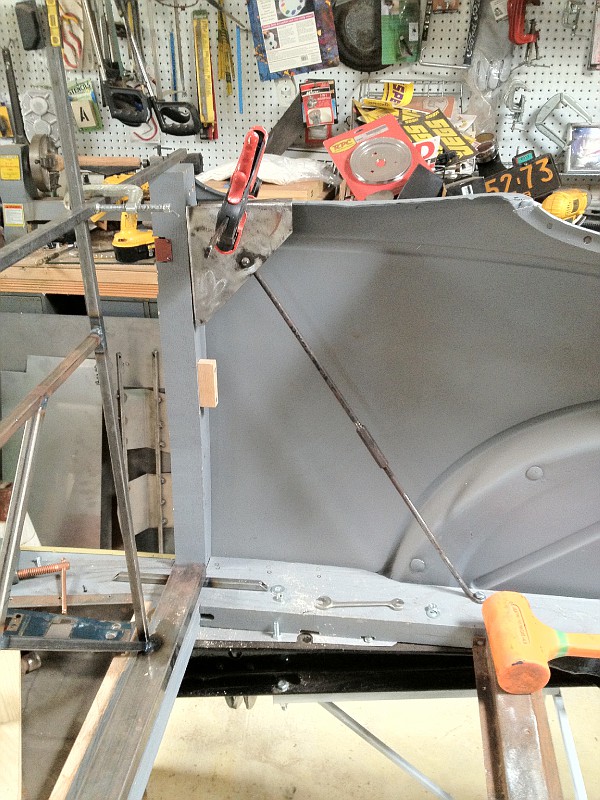 The lower triangle piece (B pillar brace), not installed, but sitting in position, facing inward, as compared to the outward facing upper piece. 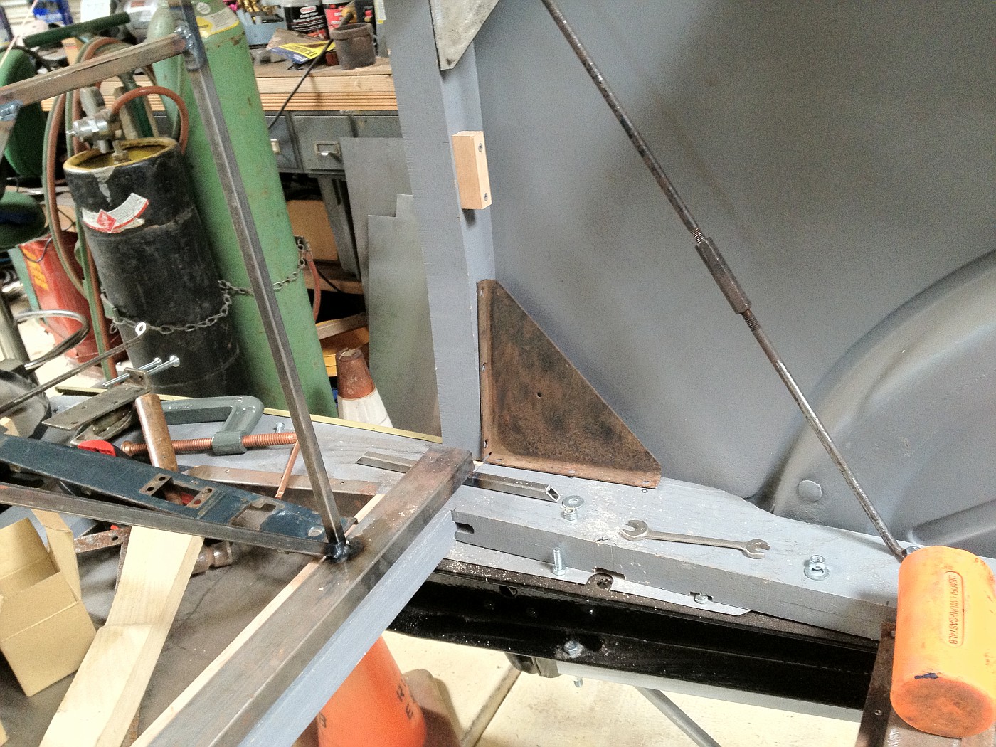 The cover (in red oxide primer) over the latch notch (on the right B pillar). Someone else may have a proper name for this piece. 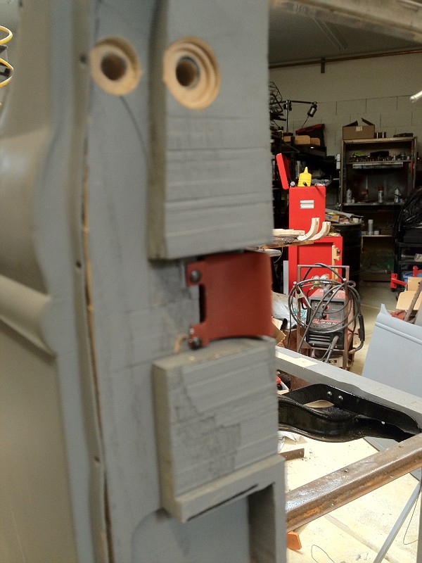 The holes above the cover piece are for mounting the triple hinge assembly. I drilled both at 5/16" though the outer one uses a 1/4" bolt. ...Just thinking it will allow slight adjustability. |
|
|
|
|
02-19-2012, 12:30 AM
|
#41 |
|
Senior Member

Join Date: May 2010
Location: Suttons Bay, Mich.
Posts: 3,392
|
I really commend you guys that work on mostly wood framed cars, this looks exhausting!! Great work.
__________________
Respecting and Resurrecting Ford Model A's. |
|
|
|
|
02-21-2012, 02:15 PM
|
#42 |
|
Senior Member
Join Date: Jul 2010
Location: Queen Creek AZ
Posts: 519
|
Nice build I will keep my eyes open as I am doing the same deal on my car
Frenchy |
|
|
|
| Sponsored Links (Register now to hide all advertisements) |
|
|
|
07-12-2012, 02:12 AM
|
#43 |
|
Senior Member
Join Date: Jul 2010
Location: Queen Creek AZ
Posts: 519
|
Any updates on your project ?
Frenchy |
|
|
|
|
07-12-2012, 04:08 PM
|
#44 |
|
Senior Member
Join Date: Feb 2011
Location: NNNNNNNNJJJJJJJJJJ
Posts: 6,811
|
Russ, thank you for those last photos. I am missing the upper triangles and cable/turnbuckles and was wondering how I was going to adjust the doors to the posts. Those photos are worth a million....
|
|
|
|
|
07-14-2012, 12:27 AM
|
#45 |
|
Senior Member
Join Date: Aug 2011
Location: Millbrae, CA
Posts: 504
|
a little update on my cabriolet body assembly.
 From the photo, it looks a little bit like there has been more progress than actual. I have made progress; but very little has been permanently assembled as fits are not as good as they should be yet. My right sill had a downward warp at the rear which required planing the bottom side back to flat, notching the upper side, laminating a thicker piece in place and trimming/planing it back to shape. I am still putting things together, looking, measuring, taking apart, adjusting, and reassembling. With my most recent assembly I got so far as to set in the package tray and seat back, and do some door fit adjustments. 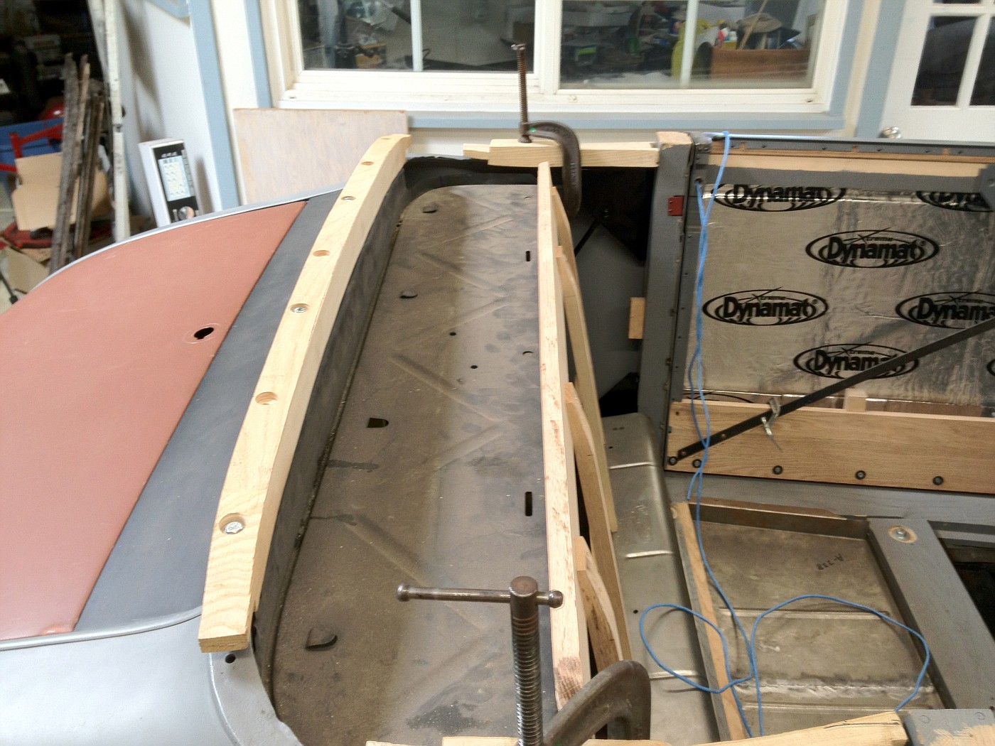 The doors are assembled to the point of having most of the wood in. I also have worked on the cowl to door gaps, getting a fairly even approximate 1/8 gap, which should be OK for paint clearance. Eystein recently posted a drawing of the 68B main sill rail and I realized some of my fit issues could be explained by my rails not having the raised area under the rumble seat pan and to the rear, as shown in the posted drawing. I laminated additional wood to the top rear of my sills and found that made a big improvement in some fits. 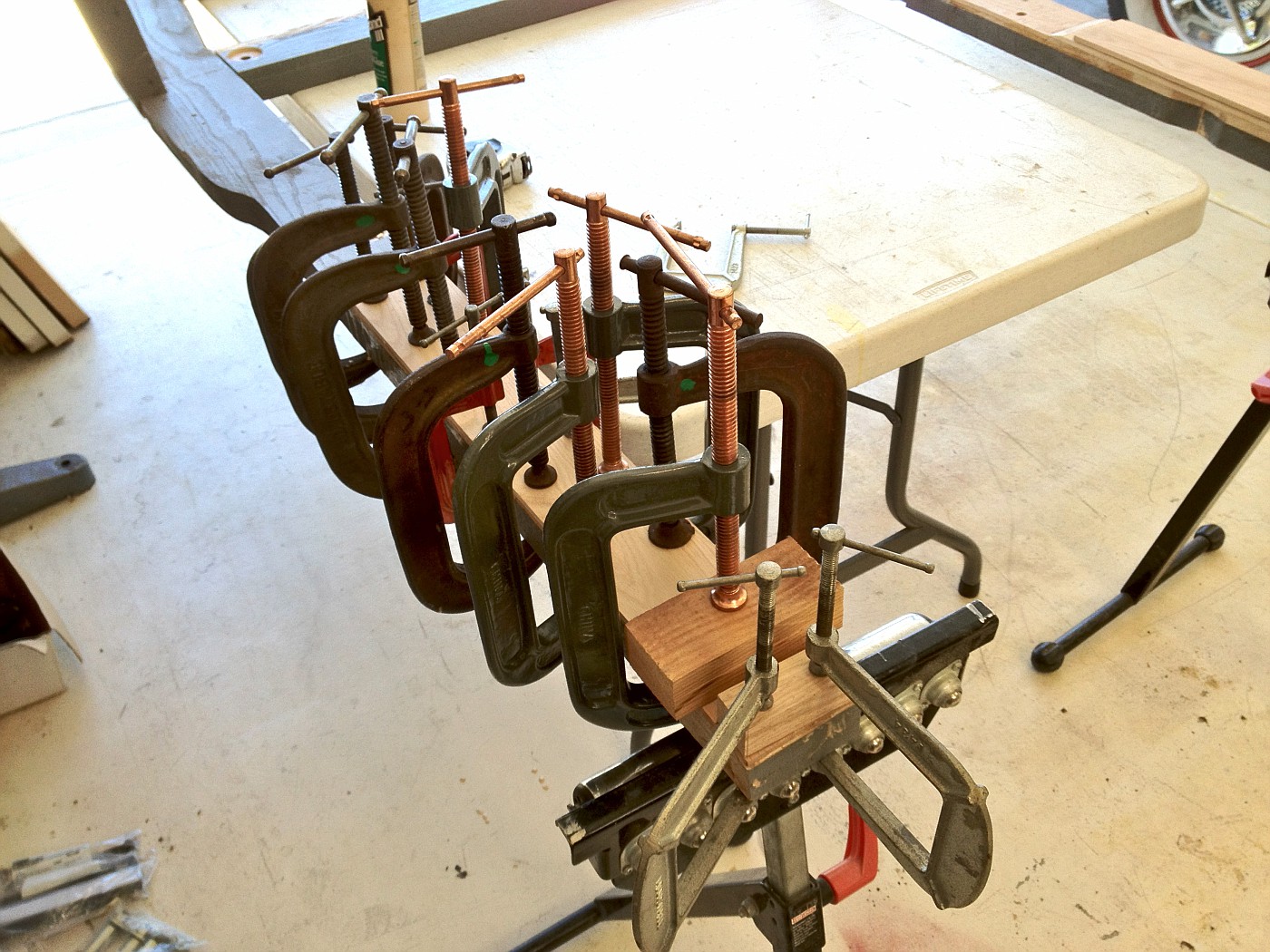 I am now getting close to good quarter panel to top of B pillar fits. Once they are good and other fit issues are corrected, I hope to nail on the quarter panels and start fitting the belt rail wood and triple hinges. 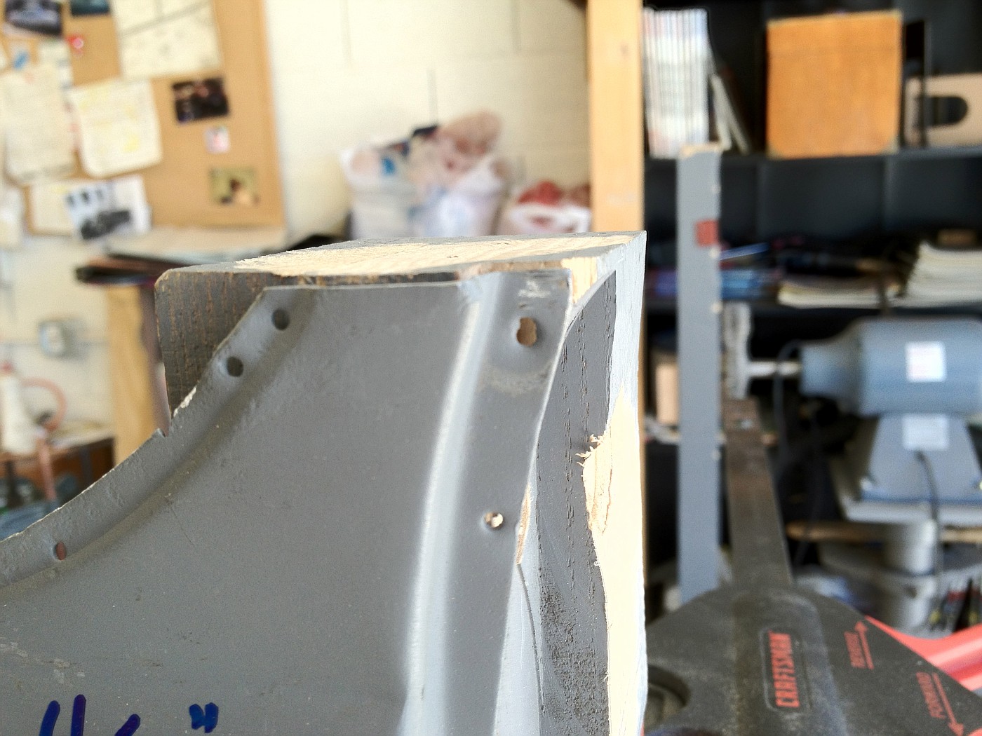 Oh, I took a quarter inch width out of my reproduction sheet metal fixed seat floor pan. It was pushing the main sill rails out too far, affecting door closing and fit of the sheet metal below the door where if meets the cowl. 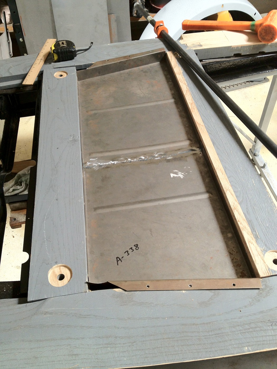 So I am still making a lot of adjustments and getting closer to real assembly. One of the things affecting my speed is that patch panels were installed on disassembled body panels nearly 20 years ago and each 1/8 misfit here and there needs to be identified and verified before I make final assembly/fit decisions on each fit issue. Thus many partial assemblies, tweaks, and reassembly. 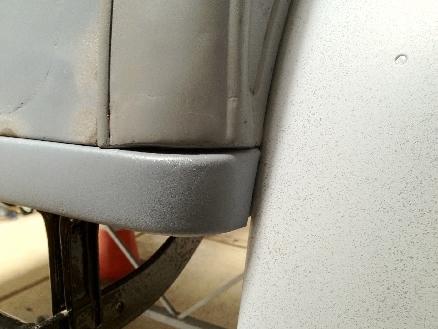 back gap of right rear quarter panel, not yet corrected Quarter panel to fender gap before: 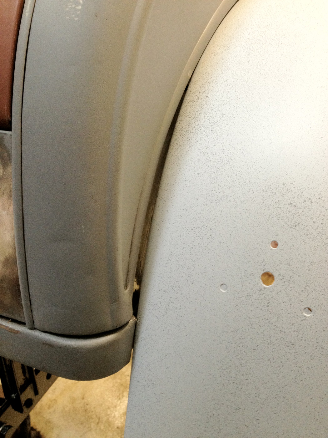 Quarter panel to fender gap after tweaking of the quarter panel:  ...but it is all fun and I am making progress. |
|
|
|
|
07-14-2012, 12:54 AM
|
#46 | |
|
Senior Member
Join Date: Aug 2011
Location: Millbrae, CA
Posts: 504
|
Sponsored Links (Register now to hide all advertisements)
Quote:
I am glad the photos have helped. The triangle pieces should be easy to make and the turnbuckle assembly with a little 'blacksmithing' of the rod ends. I have seen open turnbuckles in some 68B cabriolet assembly photos. I can pull some dimensions off my pieces if it would help. I had to do some patching of my triangle pieces and made a false rivet head on one side where the original rivet head had been almost ground off. The screw hole location to the B pillar is not critical, but on the upper flange the holes will line up with the triple hinge, and attach with 1/4," iirc, bolts, or maybe #12. I am not that far along yet. Russ |
|
|
|
|
|
07-14-2012, 01:26 PM
|
#47 |
|
Senior Member

Join Date: May 2010
Posts: 3,099
|
Russ,
I'm pretty certain the vertical boards on the seat back wood should be reversed so the angled tops face the rear and the top plank becomes vertical. I believe it's the same as '28-29 Coupes so it should be easy to confirm. As far as your door gaps, If you have a true 1/8" it will appear excessive when finished. I have a 1" wide strip of cardboard measuring about .080" thick. It's actually a panel board scrap from making interior trim panels. On my original Briggs Fordor I can slip it into the hinge pillar gaps in MOST places. On my Roadster the gaps are about .010" less. There should be no measurable paint build in those areas.
__________________
http://www.abarnyard.com/ |
|
|
|
|
07-15-2012, 09:49 PM
|
#48 | |
|
Senior Member
Join Date: Aug 2011
Location: Millbrae, CA
Posts: 504
|
Quote:
Regarding door gaps, I will shoot for 0.080 or less as I refine the door gap adjustment. I started with 3/8 on the left door gap and 0 to 1/8 on the right door to cowl gap. I am close to 1/8 now on both sides but still not at a perfect setting top to bottom. I took a few photos today of my original seat back. Maybe they will spark more discussion. I placed the seat back I fabricated with the top board to the very back as the original had all the upholstery nails on the back side. The other side with the vertical stringers forward had originally mounted the springs. the top edge of the top piece also had a round-over edge and a slight recess. Also note the vertical stringers each have a small notch that appears to be for holding the bottom of the seat back on the foldover back edge of the metal fixed seat riser.  My original seat back wood frame, not usable, but good as a pattern. 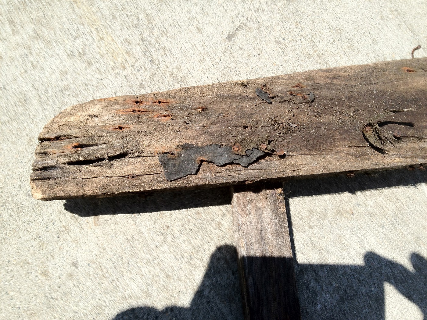 The slight recess at the top is barely visible, but is of uniform width across the top board, maybe 3/4", iirc. 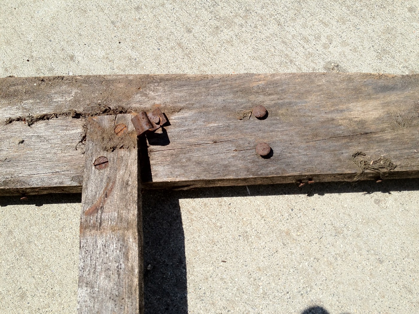 Note angle of vertical stringer and spring mounting bracket. The screws are countersunk and set the fit of the vertical boards in relation to the horizontal top and bottom. 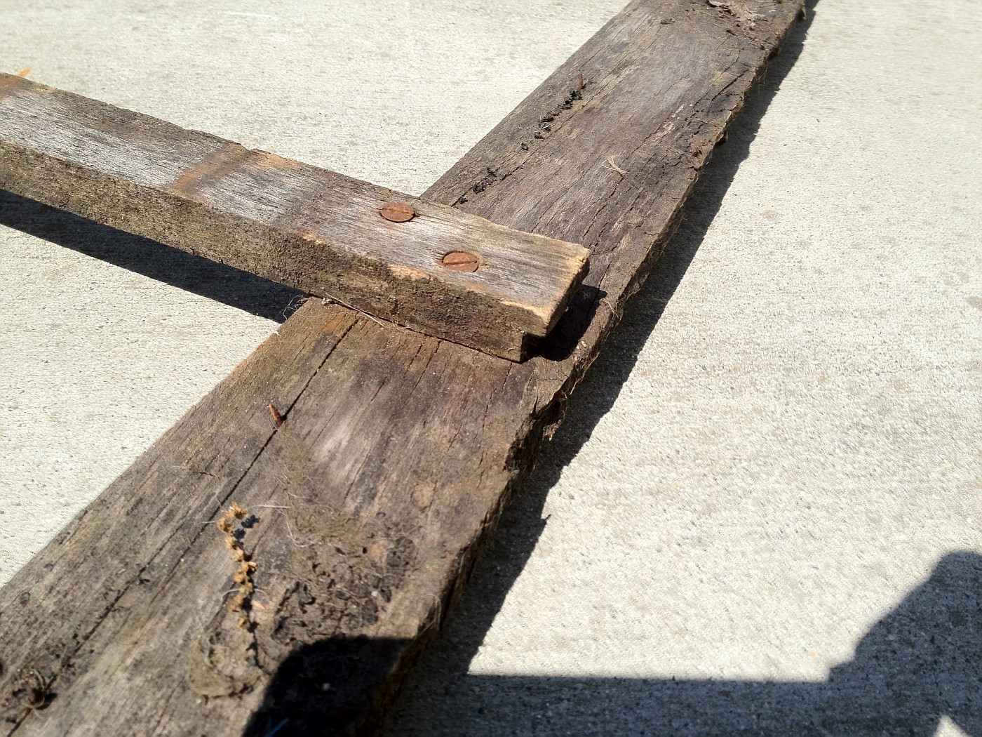 Note notch at bottom of stringer. This was typical for all. The frame construction was done as was my original. Does my placement of the seat back frame look proper when comparing to the photos of the original? Before I left it that way for progress photos, I tried it both directions and it seemed to fit best as I placed it. |
|
|
|
|
|
07-15-2012, 10:12 PM
|
#49 |
|
Senior Member
Join Date: May 2010
Location: South Florida
Posts: 14,054
|
These types of threads are my favorite!!!
__________________
What's right about America is that although we have a mess of problems, we have great capacity - intellect and resources - to do some thing about them. - Henry Ford II |
|
|
|
|
07-15-2012, 10:58 PM
|
#50 |
|
Senior Member
Join Date: May 2010
Location: Ogden Utah
Posts: 242
|
When I restored my 68B back in the early eightys I started rith the radiator and shell mounted with the proper rubber shims. I then located my cowl and matehed it up for a perfect fit with the hood. I then attached the doors to the cowl which showed me the exact placement of the door posts for a perfect fit. It all came together very nice and was a blue ribbon winner in the national in San Diago
|
|
|
|
|
07-16-2012, 05:07 AM
|
#51 |
|
Senior Member
Join Date: May 2010
Posts: 130
|
"Regarding door gaps, I will shoot for 0.080 or less as I refine the door gap adjustment."
Russ, When you are checking the door gaps be sure to have the female dovetail in place. When I was messing with the gaps, if the gap got too small then the dovetail wanted to hit the door first. Also, it seems to me that my door gaps change slightly with the weather so I set my gaps towards .100 And finally, if you are using original top irons, locking them into place also determines final door gap because the top irons will put tension towards the rear forcing the gap open if everything was not set properly to begin with. |
|
|
|
|
07-16-2012, 11:28 AM
|
#52 | |
|
Senior Member
Join Date: Aug 2011
Location: Millbrae, CA
Posts: 504
|
Quote:
|
|
|
|
|
|
07-16-2012, 04:14 PM
|
#53 | |
|
Senior Member
Join Date: May 2010
Posts: 3,099
|
Quote:
Do you have the steel "hooks" that were riveted to the upper plank?
__________________
http://www.abarnyard.com/ |
|
|
|
|
|
07-16-2012, 06:41 PM
|
#54 | |
|
Senior Member
Join Date: Aug 2011
Location: Millbrae, CA
Posts: 504
|
Quote:
On the upper plank, there are two pairs of rivets, one pair can be seen on the third photo of my earlier post(9:49 pm 7/15). There have never been any hooks as long as I have had the car. The seat back was always problematic when I was driving the car in the early 1960's. More than once I recall the seat back slipped out of position if I hit too much of a bump. I have two mortised slots in the wood bar that supports the front of the package tray, and matching slots in the package tray. These line up with the two pairs of rivets on the upper plank of the seat frame. Possibly an offset strap or hook of some sort could have been used to hold the seat back in place. Until now I had never given those slots much thought. That wood bar is the only wood in the car that has had minimal damage and that I plan to use. That wood package tray support bar is held by a bolt on each end attached to the belt rail wood. I recall other cabriolet photos I have seen seem to show the package tray supported by a strap screwed to the belt rail like my 45A's package tray. My package tray has no provision for such a strap. |
|
|
|
|
|
07-22-2012, 02:35 PM
|
#55 |
|
Senior Member
Join Date: May 2010
Posts: 332
|
Could you post a full photo of the other side of your original seat back ? Thanks , Norm
|
|
|
|
|
07-22-2012, 10:07 PM
|
#56 | |
|
Senior Member
Join Date: Aug 2011
Location: Millbrae, CA
Posts: 504
|
Quote:
|
|
|
|
|
|
07-24-2012, 03:42 PM
|
#57 |
|
Senior Member
Join Date: May 2010
Posts: 332
|
Thanks a lot. That is what I was looking for
|
|
|
|
|
04-29-2014, 11:05 PM
|
#58 |
|
Senior Member
Join Date: Apr 2013
Location: Big pine Ca 93513
Posts: 797
|
I have an original 68c body in good shape if anyone needs photos measurements of sub-frame , etc. Spencer , big pine
|
|
|
|
|
04-30-2014, 07:40 AM
|
#59 |
|
Senior Member
Join Date: May 2010
Location: South East NJ
Posts: 3,398
|
FWIW, All the lower rear panels should have the hole in them for the rear spare.
If you are doing side mounts it should have a plug in the hole. I believe the plug should be painted body color. Before you go too far with the rumble lid. Put the latch in it. The latch must fit snug to the underside of the sheet metal. The is controlled by the two screws on the face. My repro was positioned too far away from the sheet metal and caused the lid to stick up at the front edge. I welded up the holes and moved them. You will expect to need to change the height of the two braces that go under the upper cross panel. These braces will alter the in-out position of the top of the door posts. The affects the door top to bottom in-out fit. You would be wise to screw your quarter panels on to the wood tightly. Clamping the quarters in place is a mistake I made and found things did not go so good when I started tightly putting the body together. I suggest you start fitting your top parts now too. It all has to work together. I will continue to warn you that Cubel does not do his wood properly. Refer to any original wood and be sure what you see makes sense. |
|
|
|
|
04-30-2014, 08:23 AM
|
#60 |
|
Senior Member

Join Date: Oct 2013
Location: Lopez Island, Wa.
Posts: 276
|
Boy do I love the pictures, wish I could do that..one thing I saw was why was seat pan edges angled?? mine dropped in flush side to side...one thought, I think because the B piller bolts clear through the sub rail it must be in place first?? very critical to door fitting later, then wrap sheet metal around the piller and nail.. I have lots of pictures of my early 29 cabby going together but cannot make pictures work on this site...would email to anyone if they let me know their email address..
__________________
The only thing worth learning is what you learn after you know it all !! ")
|
|
|
|
|
04-30-2014, 06:07 PM
|
#61 | |
|
Senior Member
Join Date: Jul 2010
Location: Oslo, Norway
Posts: 522
|
Kevin,
Could you please explain more about the sentence below. What is the cross panel ? Is it the panel in front of the rumble lid ? Are you sure that the braces under the panel will set the door post position ? I thought that that position was set by the turnbuckles going from the corner of the quarter lock pillars and front belt rail wood down to the sills ? Anyway, adjusting the height of the braces to the panel in front of the rumble lid, needs to be done identically on both sides of the car in order to not affect rumble lid fit Quote:
|
|
|
|
|
|
04-30-2014, 08:35 PM
|
#62 |
|
Senior Member
Join Date: May 2010
Location: South East NJ
Posts: 3,398
|
I thought the same as you till I put my car together.
The door back edge angle was not matching the quarter panels. Scratched my head on this one for a while. The turnbuckles did not do much and I know now they are to give structure for the top (kind of complicated, not sure the best way to describe it). I had to make up my braces as I only had one that was missing most of the bottom and way thinner then it should be. So I go some repro ones for a different body and made up the bottom based on pictures and some guessing. Got pretty close and was fortunate in each was a bit too short. Anyway I stumbled onto the fact when you move them you change the distance across the top. Makes sense, you raise a roof you pull in the sides. My rumble lid fit was more because the side of the left quarter panel was pushed in some. This will change the shape through the rumble lid edge of the quarter. That was another head scratching week or so till I realized what was wrong. I noticed the left side was vertical from the top of the fender bead to the belt bead. While the right side, which fit good, was angled out. What I learned the most was to trust was I see as being right. You can build the cabriolet body thinking about what makes sense. You do not need all sort of measurements when building the body. You do need well made wood that is fairly accurate or you add hours/days/weeks to trying to figure out how to put the body together. So if you notice I talk about how the wood should be. It is not because I want JS perfect- it is because I found if the wood is right the darn car will just go together. When it is wrong it is a fight!!! I have done a lot of fighting with wood. So much after that becomes making it look right. A note on turnbuckles. They have more to do with the tensions caused by the flex of the frame and how the top connects to the top of the cowl. It becomes a tight box structure with a lot of power to distort. The turnbuckle stabilize the top of the door post from rocking. This coupled with the door dovetails (I speak a lot about how these MUST function properly too) you keep the body from tearing itself apart. At least that is what I believe is happening. In any event, I still have much to learn so take what I say and check that I am right. My final test comes when I finally put a top on the body. Going to be a while unless some wealthy person (I do not have any wealthy relatives) gives me a pile of money or a full interior and top 
|
|
|
|
| Sponsored Links (Register now to hide all advertisements) |
|
|
|
05-01-2014, 07:31 AM
|
#63 |
|
Senior Member
Join Date: Jul 2010
Location: Oslo, Norway
Posts: 522
|
Kevin,
I have had a lot of use of measurements, and consider the original drawings of the wood as being the single best purchase I have made for my car. It has allowed me to correct all the problems in the wood that I purchased from Classic Wood (refer to my post on modelahouse) I have found that when correcting the wood according to the original drawings it most often solves problems of fit to the sheet metal. That being said, the right quarter panel had to have "only" 50% of the metal replaced. - The left panel needed more....... So, obviously, in this case, not everything was spot on after the repair on the panels was complete. In order to find out what is wrong with the sheet metal and adjusting it to where it should be, it has been a great help to first check and correct the wood according to the original drawings and then to correct the sheet metal accordingly. The wood drawings with all their measurements have been like a map to show me if I am on the right course or not. As to the quarter lock pillars (door posts) I have locked them firmly in place to each other in the exact mutual position as given by the original drawings. This I have done by a solid piece of plywood as shown in the photo (works well as a backrest for my son too )(Btw. one of the superb features of the original drawings is that they include exact measurements of the position of each peace w.r.t the centerline of the body, and the front line of the cowl, thereby telling you how everything should fit together) All the fitting of the quarter panels, door gaps and belt rail wood has been done with the pillars locked in position like this. I am thinking that when I finally mount the pillars, I will "cast" them into this position by using epoxy to the sills, so that minute imperfections in the fit of the mating surfaces will not distort the positioning once the plywood is removed. So, as far as I see it, it will depend on the tension in the panels, and whether any residual tension will pull the pillars out of position when the plywood is removed. It does not seem too bad to me, and I have currently cut 4-5 slots in the sheet metal and reinforcement in the q-panel lip under the belt rail wood, in order to releave metal tension when pulling the curvature of the panel top edge into alignment with the forward belt rail wood. |
|
|
|
|
05-01-2014, 08:32 AM
|
#64 |
|
Senior Member
Join Date: Oct 2013
Location: Lopez Island, Wa.
Posts: 276
|
here is picture of sub rails I built out of oak, big question is B piller location in relation to cowl so doors fit..think cowl is key since frame holes position the cowl?? Love the pictures..DSC_0009-007.JPG
__________________
The only thing worth learning is what you learn after you know it all !!
|
|
|
|
|
05-01-2014, 10:18 AM
|
#65 |
|
Senior Member
Join Date: Jul 2010
Location: Oslo, Norway
Posts: 522
|
Carguy,
I started with checking with the drawings that the notches at the front where the rear edge of the cowl were correct with respect to the frame mounting holes, and that they were exactly parallel left-right. Then I mounted the cowl and hung the doors, adjusted the door to cowl gaps parallel, and then shimmed the cowl to make the bottom of the doors parallel to the sills. Then, I put on the quarter panels temporarily, making sure that they were perfectly fitting to the quarter lock pillars and fastened with tiny wood screws to the pillars top and bottom. Pillars were locked to each others according to drawing dimensions by the plywood plate mentioned in the previous post. The top of the pillars were positioned to the exact height above the sill line according to drawing dimensions, by mounting the bottom triangular braces to the pillars, and resting, (but not yet bolted), on the top of the sills. Then I adjusted the door gap by moving the pillars back or forth and shimming with this slices of wood. (The cutouts for the pillars in the sills were oversize in the front-rear direction) In addition, I corrected the shimming of the cowl to make the belt line beads align from doors to q-panel. The rear of the body was shimmed to make the door to q-panel gap uniform top to bottom. With the quarter lock pillars positioned and locked in place by shims, I moved to the rear. I found that by positioning the rear body cross member according to drawings, the quarter panels now fit almost perfectly. The panel under the rumble lid was mounted to the rear crossmember, and the quarter panels were bolted to the panel under the lid. Then I mounted the rear inner q-panel braces with C-clamps to the sills, the curved inner panel and the rumble lid. At this point, you can make slight adjustments by tapping the rear crossmember back and forth. - Make sure to watch the rumble lid fit. When everything was fine, I drilled the holes fastening the rear crossmember and the rear q-panel braces to the sills. I also corrected the height of the front q-panel braces to make the top of the deck level such that the rumble lid would close level to the opening. Then I moved to fitting the belt rail wood which is what I am doing right now. In general, throughout the process, it is very important to keep the sills shimmed and tied down firm to a straight frame. Also, the bottom of the q-panels should be hugging the sills both vertically and horizontally- use C-clamps. And -expect to mount and dismount everything about a gazillion times, and remember that everything has to be checked with everything in place before you may dare to claim that you're done. -It's a highly iterative process, fixing just a few new points every time around. |
|
|
|
|
«
Previous Thread
|
Next Thread
»
 Linear Mode

|
|

| Sponsored Links (Register now to hide all advertisements) |
|
|
All times are GMT -5. The time now is 12:54 PM.