|
|||||||


| Sponsored Links (Register now to hide all advertisements) |
|
|
 |

|
Thread Tools | Display Modes |
 10-25-2012, 07:46 PM
|
#1 |
|
Senior Member
Join Date: May 2010
Location: Lakeville, MN
Posts: 5,159
|
When the 2011 version of the judging guideline came out, there was an added throttle control assembly (from 6 versions and now 7) - page 1-17 (see picture below). I have a roadster made in September 28. The car falls into the range where the "added" throttle assembly was added to the JG's - June 1928 through September 1928. The new JG's addition is very similar to the next version (style 3) except the second version has stiffening ribs on it. I was at Hershey this year and I must have looked through over 200 throttle assemblies and never found one like the second style. I am wondering it the second style is a "phantom" assembly. If anyone has a car with the second version, would you please post a response to this post, so I know they really exist. I have friends that have never seen one either. Also, if anyone knows anything about the second version, I would like to know about it. I have seen a number (not a lot, however) of the first version (and have had 4 of them) that also has stiffening ribs on it and plenty of the third through seventh versions, but zip for the second style. I know any throttle assembly would work OK, but I am trying to restore my cars to near fine points so I would like to use the correct parts on them. Any information would be appreciated.
Rusty Nelson 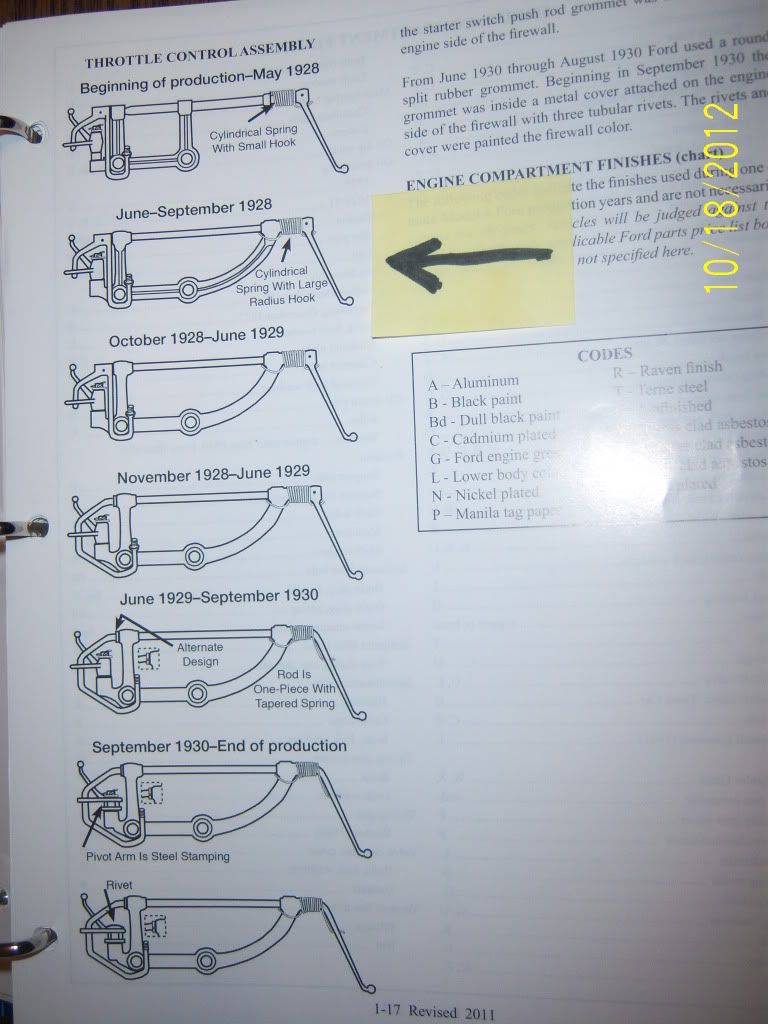
|

|

|
|
10-25-2012, 10:17 PM
|
#2 |
|
Senior Member

Join Date: May 2010
Location: Mpls, MN
Posts: 27,582
|
I also have never seen the second version.
I have the first version, but will have to look at it again, because I don't remember it havlng the ribs either. My Sept 1928 Phaeton has the original engine and it has the third one shown in your pictures. Correction, my 28 Phaeton has the one I pictured in post 22, which as sphanna says isn't pictured in the J/S. Last edited by Tom Wesenberg; 10-29-2012 at 07:28 PM. |
|
|
|
| Sponsored Links (Register now to hide all advertisements) |
|
|
|
10-25-2012, 10:43 PM
|
#3 |
|
BANNED
Join Date: May 2010
Location: Gothenburg Nebraska Just off I-80
Posts: 4,893
|
I do not have the current JS yet so this is news to me. I will look through my throttle assemblies and see if I have one of these. It has been quite some time since I have looked at them. Rod
__________________
Do the RIGHT thing - Support the H.A.M.B. Alliance!!!! |
|
|
|
|
10-26-2012, 01:24 PM
|
#4 |
|
Senior Member

Join Date: May 2010
Location: Fresno, Ca.
Posts: 3,636
|
My mid August 28 also has the 2rd. style which "holds no water" since the
engine and transmission were changed out long before I purchased it in 1965. I suspect it is a fabricated assembly, similar to the 1st style, and not a forging like the 3rd thru 7th styles.....but that's just a guess, I never have seen one also. I would (Rusty, I'm sure) like too see photos of this "phantom" critter? Last edited by d.j. moordigian; 11-13-2012 at 07:05 PM. |
|
|
|
|
10-26-2012, 11:48 PM
|
#5 |
|
Senior Member

Join Date: May 2010
Location: Englewood, Colorado
Posts: 1,372
|
Rusty,
I looked thru about 150 throttle assemblies we have, to try to find one for you,and their were none of that style. Had several of the early ones and numerous of all the others, but I too have never seen one. When you sent me a request to look for one, I too realized that I have never seen one of that type either. Steve Becker Berts Model A Center |
|
|
|
|
10-27-2012, 08:37 AM
|
#6 |
|
Senior Member
Join Date: May 2010
Location: Lakeville, MN
Posts: 5,159
|
Sponsored Links (Register now to hide all advertisements)
Thanks for looking, I appreciate it. I am starting to think the second version is a "ghost" part. It wasn't in the JG's until the 2011 revision. I know they were supposedly used for only 3 or 4 months, but still it would seem that a few would show up at Hershey (I must have looked at over 200 throttle assemblies and none found) or in your cache of throttle assemblies at Bert's. According to Steve Plucker's engine production chart, about 300,000 engines (cars??), were made from June 28 through September 28. That is a fair amount of throttle assemblies used. I will let you know if I find one, but I am not banking on finding one any time soon, if ever. Rusty Nelson |
|
|
|
|
10-27-2012, 11:47 AM
|
#7 |
|
Senior Member

Join Date: Aug 2010
Location: Port Orchard, WA
Posts: 1,498
|
I think this item was made out of a hard to find material from the 20’s referred to as “un-obtainium”
Last edited by 160B; 10-27-2012 at 11:58 AM. Reason: spelling of un-obtainium corrected |
|
|
|
|
10-27-2012, 12:36 PM
|
#8 |
|
Senior Member
Join Date: May 2010
Location: Fresno, Ca.
Posts: 3,636
|
Well...between Rusty, Steve and my self, we looked at about 500 assemblies. Interesting, too say the least!
I have found a way too circumvent the problem on my car. The "60 day rule"! My car's engine is 60 work days from the last day in May...neat....I can use the First style Throttle assembly! Now for the next question on the "60 day rule"......do we have to count weekends? ")
|
|
|
|
|
10-27-2012, 01:47 PM
|
#9 | |
|
Senior Member
Join Date: Aug 2010
Location: Port Orchard, WA
Posts: 1,498
|
Quote:
|
|
|
|
|

|
10-27-2012, 05:42 PM
|
#10 | |
|
Senior Member
Join Date: May 2010
Location: Fresno, Ca.
Posts: 3,636
|
Quote:
shipping? It would have had a flywheel housing, flywheel and a throttle ass. too test run the engine. Also the clutch and pressure plate assemble and maybe starter? Now...back too the " Second version of the throttle assembly",...who has photos? |
|
|
|
|
|
10-27-2012, 06:32 PM
|
#11 |
|
Senior Member

Join Date: Jun 2010
Location: Polk City, Iowa
Posts: 526
|
I have a throttle control assy. that is different from all the 7 pictured in the above posts. I will try to post a picture. Any information about this one? It came off an engine numbered A2162368.
As you can see, the bottom goes straight to the edge at the left of the picture. It looks mostly like the top picture except there is the curved extention to the upper right top. Also I am wondering if any or all will work for any year if not for show.
__________________
Steve Hanna, Polk City, IA Last edited by sphanna; 09-29-2014 at 07:42 PM. |
|
|
|
|
10-27-2012, 07:21 PM
|
#12 |
|
Senior Member
Join Date: May 2010
Location: Lakeville, MN
Posts: 5,159
|
Steve,
I see what you mean. It looks very close to the third version, except for the lack of a curved up area in the lower left side. Maybe there were several venders that made the assemblies and they took a little liberty with the design. I will check my 5 or 6 version three assemblies and see if any look like the one in your picture. I suppose the people that wrote the JG's will add one more assembly to the guidelines - ha ha. The plot thickens!! I was hoping some Fordbarner that had a car made between June 28 and Sept 28 that was not molested would respond on what throttle assembly was on their car. Rusty Nelson |
|
|
|
|
10-27-2012, 07:50 PM
|
#13 | |
|
Senior Member
Join Date: Aug 2010
Location: Port Orchard, WA
Posts: 1,498
|
Quote:
The lower left side looks more like the first version. 2162368 would be an August 19,1929 engine I always wondered how hard the pattern maker worked to revise the old patterns to the new version. Looks like the pattern maker got the update correct for the curve on the RH side but did not change the pattern on the LH side to add the radius corner. If you look at the first version of the pivot arm with a spacer below it is exactly like the one in the photo you posted. Last edited by 160B; 11-01-2012 at 07:56 PM. Reason: Added comment on pivot arm & mfr date for engine |
|
|
|
|
|
10-28-2012, 01:23 PM
|
#14 |
|
BANNED
Join Date: May 2010
Location: Gothenburg Nebraska Just off I-80
Posts: 4,893
|
Looked at the 23 I have and the second style does not exist in my parts pile. Thinking this may exist in drawing form only. Rod
__________________
Do the RIGHT thing - Support the H.A.M.B. Alliance!!!! |
|
|
|
|
10-28-2012, 01:24 PM
|
#15 |
|
Senior Member
Join Date: May 2010
Location: Lakeville, MN
Posts: 5,159
|
160B,
I looked though my 12 to 14 throttle assemblies and for the style 3 assemblies. I found 5 that are like the one you posted a picture of and 2 that are like the JG's. Go figure. I posted a picture of the two assembles below. It is kind of wield that out of 7 assemblies of the third type, 5 are different from the JG'S and 2 are the same. Rusty Nelson 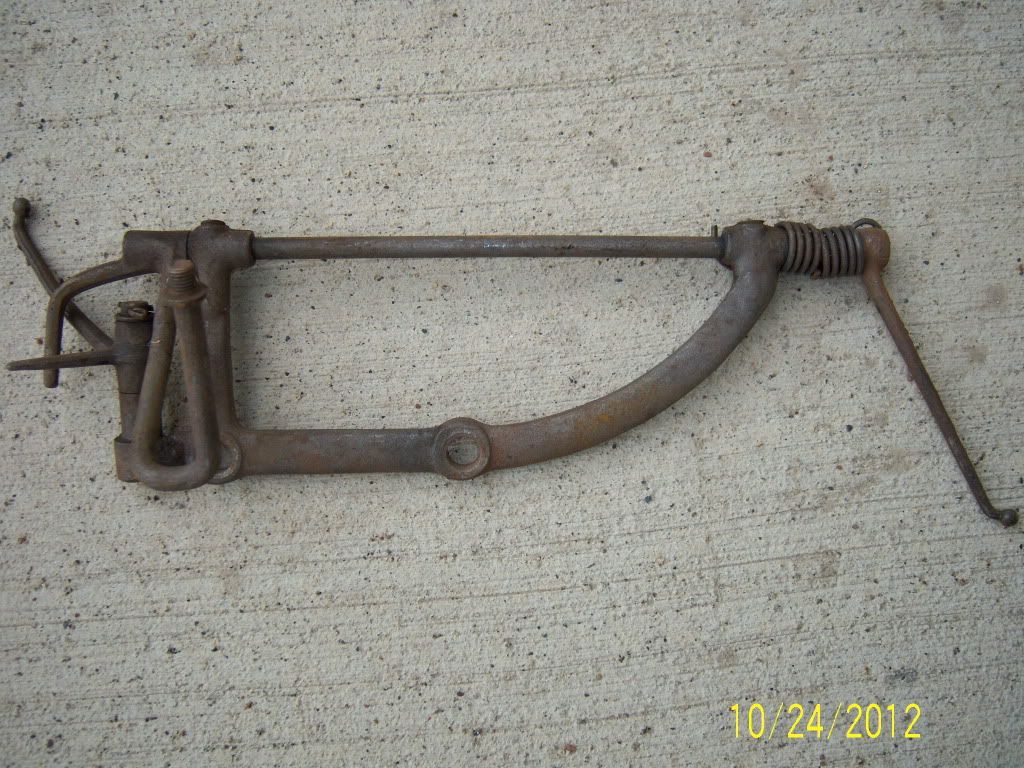 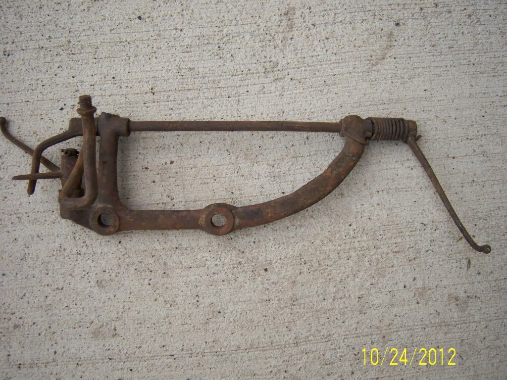
|
|
|
|
|
10-28-2012, 02:12 PM
|
#16 |
|
Senior Member
Join Date: May 2010
Location: So Cal
Posts: 8,743
|
Rusty, I wonder if the one in the lower picture came after the one in the top picture as
it eliminates the spacer under the bell crank saving Henry money. Bob |
|
|
|
|
10-28-2012, 02:21 PM
|
#17 | |
|
Senior Member
Join Date: Aug 2010
Location: Port Orchard, WA
Posts: 1,498
|
Quote:
It makes you think that there might be something that was missed when the JS's were revised. It is interesting that no one has a throttle assembly similar to style 2, but in the small number of Fordbarners on this post they have produced 6 of a design that is not in the JS??? Last edited by 160B; 10-28-2012 at 02:23 PM. Reason: deleted the photos in the qoute |
|
|
|
|
|
10-28-2012, 03:25 PM
|
#18 |
|
Senior Member
Join Date: May 2010
Location: Lakeville, MN
Posts: 5,159
|
Sorry 160B,
My mistake. I should have check a little more. If that were my only mistake, I would be a happy man! Rusty Nelson Last edited by wrndln; 11-09-2012 at 08:57 PM. |
|
|
|
|
10-28-2012, 03:28 PM
|
#19 | |
|
Senior Member
Join Date: Aug 2010
Location: Port Orchard, WA
Posts: 1,498
|
Quote:
No apolgy necessary!! I was trying to make sure that individual who posted the photo was noted correctly. |
|
|
|
|
|
10-29-2012, 09:33 AM
|
#20 |
|
BANNED
Join Date: May 2010
Location: Gothenburg Nebraska Just off I-80
Posts: 4,893
|
Since so far none of the second style have been postes as found it would be nice if someone from the Js committee would come forward and show us what research prompted the change. Rod
__________________
Do the RIGHT thing - Support the H.A.M.B. Alliance!!!! |
|
|
|
|
10-29-2012, 01:05 PM
|
#21 |
|
Senior Member
Join Date: May 2010
Location: Lakeville, MN
Posts: 5,159
|
Rod,
Thanks for looking through your stash of throttle assemblies. I can't believe not one second version assembly has surfaced in this discussion. I agree, it would be nice if some people from the judging guideline committee would chime in and state if they had one to make the sketch in the guidelines or it was just someones memory of seeing one in the past. Rusty Nelson |
|
|
|
|
10-29-2012, 07:25 PM
|
#22 |
|
Senior Member
Join Date: May 2010
Location: Mpls, MN
Posts: 27,582
|
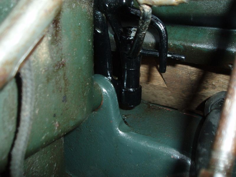 My 9-27-28 has the same one sphanna posted in #11, so I'm thinking this is the second design, and the second picture in the J/S may not exist. Also notice my washer and cotter pin are missing from the linkage. 
|
|
|
|
| Sponsored Links (Register now to hide all advertisements) |
|
|
|
10-29-2012, 10:41 PM
|
#23 |
|
Senior Member
Join Date: May 2010
Location: Lakeville, MN
Posts: 5,159
|
Thanks Tom and Don for your posts.
Tom, assuming your Sept 28 A hasn't been messed with, it should have version 2, but doesn't. I am starting to think the second version might have been a part that was never produced - maybe drawing only? Don, Thanks for the information about the throttle assemble concerning the JS Committee. Rusty Nelson |
|
|
|
|
10-30-2012, 10:07 AM
|
#24 | |
|
Senior Member
Join Date: May 2010
Location: Fresno, Ca.
Posts: 3,636
|
Quote:
assembly! Sorry, I didn't look for a part number, the "flu" has a good grip on the body... |
|
|
|
|
|
11-01-2012, 04:11 PM
|
#25 |
|
BANNED
Join Date: May 2010
Location: Walla Walla, Washington USA
Posts: 6,066
|
I agree with Rowdy...How about it MARC/MAFCA Judging Standards Committee Members...what is the story on these?
OPPS...SORRY DID NOT SEE DON'S POST BUT IS THERE MORE TO THE STORY? Pluck |
|
|
|
|
11-13-2012, 06:12 PM
|
#26 |
|
Senior Member

Join Date: May 2010
Posts: 3,099
|
Sponsored Links (Register now to hide all advertisements)
As I noted in the other related thread by Steve Plucker, the drawing and info on the "type 2" depicted in the Standards was likely direct from a Ford drawing. However I have a few examples of such drawings where the item was either never put into production in exactly the depicted form OR was used so briefly that matching items cannot be found. To make it even more interesting, the version that WAS produced during the described period not only did not quite match any drawing, the unique characteristics of the production version are not even described in the detailed engineering changes. They made many changes on the fly (especially in 1928) that were either documented much later or superseded before ever being recorded in their exact form. I've been compiling bits of information and comparing notes with Doug Clayton. It's quite clear that the depicted version for #2 was either never produced or was done so for such a brief period it almost becomes moot. Here is how it looks at this point in time. The A-9725 throttle control assembly was made from several pieces with the primary part being the A-9728 Accelerator Bracket. The bracket was initially a steel forging which is extremely strong but relatively expensive to produce depending on the shape. Later the bracket was changed to a malleable casting. Type 1 (early '28) clearly used a forged bracket. In doing my homework I discovered that for a short time (not precisely defined) Ford made the bracket from TWO forgings, A-9748 right half and A-9749 left half. That is what you will clearly see in the photo below from Steve Hanna. Note the weld seam as well as the sharp small forging ID marks to the right of the right mounting hole. This is what I believe is the actual type 2, or at the very least type 2-b quickly replacing the depicted version. Closely coinciding with the introduction of the type 2 there were two additional parts added. These were A-9731 Oil Wick and A-9733 Oil Plug. I'm guessing the "plug" was the cup that was pressed into the oil holes on the top of the bracket and the wick was a piece of felt. This was brought to my attention in a pic from Tom Wesenberg a few years ago. These APPEAR to be present in the pic below from Rusty. I can't tell for sure if this assembly is a forging or the newer casting. Some two piece brackets have more subtle welds and need to be looked at very closely. Hopefully Rusty can add some info. If it's a two piece forging it's essentially the same as the one shown above. If it's a casting then I'd call it type 3-a. Note the "flat bottom" below the bell crank. Here is the second pic from Rusty. Note the change in the bracket supporting the bell crank. It no longer has a flat bottom. This is the traditional type 3 which may be "3-b" depending on the answer to my question above.
__________________
http://www.abarnyard.com/ |
|
|
|
|
11-13-2012, 06:49 PM
|
#27 |
|
Senior Member
Join Date: May 2010
Location: Fresno, Ca.
Posts: 3,636
|
Marco,
I have the type1 style "throttle" ass. and what I consider the type 2 "flat bottom" style. The type 2, "felt" is below the the shaft, in the oilier holes. Yes, 2 piece forging, along with all the arms, except for the arm that the "button" is screwed to,it is half forging and half steel rod welded together. The left half of the bracket has the forging number A-9749 on the vertical leg. Dudley Last edited by d.j. moordigian; 11-13-2012 at 08:24 PM. |
|
|
|
|
11-13-2012, 08:28 PM
|
#28 |
|
Senior Member
Join Date: May 2010
Location: Lakeville, MN
Posts: 5,159
|
Thanks Marco for looking into the throttle assembly question. I dug through my stash of throttle assemblies again and found two forgings or casting of the style that has the straight area below the bell crank. One is like Steve Hanna's - welded together which is the first picture below. The place that is welded is where Steve's is joined, however it is a little hard to see, but it is there. The second picture is an assembly with a straight area below the bell crank forging or casting and is one piece. I am sure the second assembly is one piece unless the maker of it was so perfect, that no trace of a welded joint remains as there are no grind marks or remnants of where the joint would have been. This would mean that there are at least two styles of the straight type. It just keeps getting stranger.
Rusty Nelson 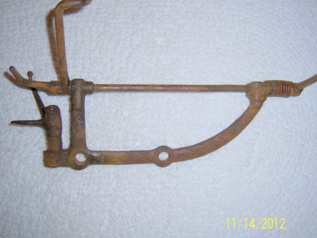 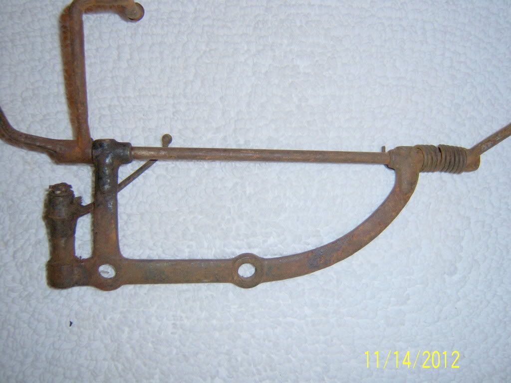
Last edited by wrndln; 11-13-2012 at 08:37 PM. |
|
|
|
|
11-13-2012, 09:32 PM
|
#29 |
|
Senior Member
Join Date: May 2010
Location: Fresno, Ca.
Posts: 3,636
|
Rusty, here you go........see the "flash line" on the inside(top of the bottom part of
the bracket...that's a forging line). Also note the black speck in the center of the photo, that is the "felt". Last edited by d.j. moordigian; 11-13-2012 at 09:38 PM. |
|
|
|
|
11-13-2012, 10:09 PM
|
#30 |
|
Senior Member
Join Date: May 2010
Location: Mpls, MN
Posts: 27,582
|
  I think these might be the photos I showed to Marco some years ago. The one shows the stamped steel oil cups which are pressed into the holes. This is the one that came on my 9-27-28 Phaeton. The other picture shows the weld seam on a similar style with the flat bottom and spacer for the bell crank. |
|
|
|
|
11-14-2012, 10:34 AM
|
#31 |
|
Senior Member
Join Date: May 2010
Location: Fresno, Ca.
Posts: 3,636
|
The "spacer" on the vertical shaft for the bell crank is part of the shaft, machined
from one piece of material. In photo #29, the shaft that goes from one end to the other(with the forged arm pinned too it), there is a " split sleeve spacer" slid onto the shaft. Tom,...great photo of the "oil cup",...never seen one. Thanks |
|
|
|
|
11-15-2012, 02:00 PM
|
#32 |
|
Senior Member
Join Date: May 2010
Location: Fresno, Ca.
Posts: 3,636
|
Marco,
When was the,.." A-9733 OIL PLUG" first introduced? I don't remember seeing one. Tom's "forged" example doesn't have one / missing,...his "cast" one does. Dudley |
|
|
|
|
11-15-2012, 02:07 PM
|
#33 | |
|
BANNED
Join Date: May 2010
Location: Walla Walla, Washington USA
Posts: 6,066
|
Quote:
Pluck |
|
|
|
|
|
11-15-2012, 07:10 PM
|
#34 |
|
Senior Member
Join Date: May 2010
Posts: 3,099
|
This is good stuff guys! I've got more to add as well as a few questions. This is still early in the process.
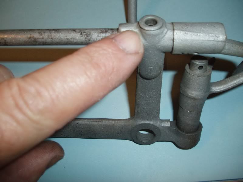
In my notes below I will toss in a couple dates from the records. It is IMPORTANT to realize those dates only offer a guide as to original intent at best and actual usage may be either earlier or later, or both. 1. My research indicates the oil wick and cup as shown in Tom's pic came into play pretty early and MAY be in the last version of the type-1 control. That would likely mean a slightly different forging shape to allow space for the wick pocket. This would be a type-1b if it exists. 2. It's now my understanding there IS an existing example of the illustrated type-2 except it SHOULD have the flat bottom as opposed to the way it was drawn. This would be type-2a and should include the oil wick and cup. I still need to confirm the existence. 3. Type-2b would be the one piece forging as shown in Tom's pic with the oil cups shown here. Also Rusty didn't respond to my curiosity on what appears to be inserts in the oil holes in the next pic. The oil "plugs" as well as the wicks were first documented 4/5/28. The plugs were documented as obsolete 7/30/28 and the felt oil wicks obsolete 2/11/29. Assuming the plugs are indeed the cups we see in some one piece forged brackets that makes them among the earliest of the"type-2" assemblies.   4. Dudley brought out some good info with his pic below and corresponding notes. If I understood correctly my added notes should be useful. This is the two piece forging which I will call "type-2c". I've not found much info on the two piece except supposedly it was obsolete 9/28/28. I suspect it was continued longer.  5. Now a note about forgings vs. castings. Folks confuse forgings with castings due to the texture on the surface of the finished product. I won't get into malleable or nodular casting but in simple terms it's it's still pouring a molten alloy into a mold of some sort. In simple terms, forging is the reshaping of solid chunks of steel under extreme heat, generally between two dies (hence the parting line). The latter is unquestionably far stronger but limited in the type of shapes that can be produced. Forging also retains the grain of the original steel over the length of the item. This is much like the grain of a strip of lumber and it's strength along the grain. If you steam bend such a board into a "U" shape the grain follows that shape and the strength is retained.  The cast version should be slightly thicker throughout but in the pic above I've outlined differences that SHOULD consistently define one from the other. At the present time I strongly suspect the forged bracket was used into early 1929. That may be a stretch but with the help of you guys looking at some cars it should be easy to nail down.
__________________
http://www.abarnyard.com/ Last edited by Marco Tahtaras; 11-15-2012 at 07:23 PM. |
|
|
|
|
11-15-2012, 07:55 PM
|
#35 |
|
Senior Member
Join Date: May 2010
Location: Fresno, Ca.
Posts: 3,636
|
Marco,
You have 1 thing incorrect the "split sleeve" is a spacer that buts up against the passenger side of the assembly,...it's hidden by the spring. |
|
|
|
|
11-15-2012, 08:11 PM
|
#36 |
|
Senior Member
Join Date: May 2010
Location: Lakeville, MN
Posts: 5,159
|
Marco,
I didn't know you wanted information from me on the second picture in the above post. I just checked the throttle assembly in the second picture and there ARE oil cups with small holes in the bottom of each cup in both places. Of the 5 or 6 throttle assemblies of this type I have, this is the only one that has oil cups. The rest just have holes in the forgings or castings. I didn't check the diameter of the holes in the other assemblies to see if there might have been cups present in the past. I think the cup type assemblies probably have a little larger hole for the cups to fit in. The throttle assembly with the oil cups looks like a forging as there are grind marks on the edges where it looks like someone ground off the excess material. I don't think casting are usually ground like that, but I could be wrong. BTW, I measured the mounting bosses and the bosses on the assembly in the second picture of mine Marco posted are just slightly less the 5/16", which I guess means it is a forging. Rusty Nelson |
|
|
|
|
11-15-2012, 08:32 PM
|
#37 | ||
|
Senior Member
Join Date: May 2010
Posts: 3,099
|
Quote:
Quote:
I need to review what I posted (or forgot to) but after spending more than half a day on this I need to give it a couple days. However here are a few thoughts / questions. 1. I would think those (and only those) with the cups will have the tops ground or machined flat for the cup as noted on Tom's pic. 2. I'm suspecting NO two piece forgings have the cups. We know SOME one piece forgings have the cups but do all of them? If not, were they flattened (ground) or otherwise prepared for cups?
__________________
http://www.abarnyard.com/ |
||
|
|
|
|
11-16-2012, 03:55 PM
|
#38 |
|
Senior Member
Join Date: May 2010
Posts: 3,099
|
OK Guys,
We're on a roll here but I need help to keep it moving forward and attempt to establish a timeline. I've stated several preliminary conclusions. I suspect most will prove to be true but confirmation is important. I didn't emphasize that the unknowns or suppositions were actually questions which I need help confirming or filling in blanks. I'll specify some of the needs here so folks can see if they can help. For those with a stash of throttle controls: 1. Oil wick cup - I didn't ask yet but wonder if those that do have the cup in place may have a felt wick between the cup and the shaft. Can you see the shaft looking through the hole in the cup? If it's been blasted there may still be part of the felt caked around the edges. 2. Oil wick cup or no oil wick cup - I showed the two-piece forging vs. the one piece. Don't confuse a cast version, I show how to distinguish them above. - Are there any one-piece forgings WITHOUT the cup? - Are there any two-piece forgings WITH the cup? It appears those with a cup were prepared for it by grinding or machining the top surface perfectly flat for the rim of the cup to seat on while others likely remain irregular. The hole may be bored larger than non-cup units as well. Any finding on this is useful 3. Interested in any other variants (even seemingly subtle) of the two forged types and first cast type as outlined above. For those with early 1928 through early '29 cars: 4. Ok, this is pretty simple EXCEPT it may be difficult to spot the seam on the two-piece forging from the engine compartment on the drivers side. It may be doable with a flashlight and mirror. We really need to know which of the types outlined above are present including the presence of oil cups or not, along with the best available date reference of the vehicle. Original engine/frame number is most useful, but a gas tank date offers some value. Obviously many cars have mismatched parts for various reasons so results will be mixed. This can generally be sorted out. Lastly, I forgot to mention that it's entirely possible that two types were both used for a period of time as alternate designs although part number suffixes don't support that. If we receive a large enough sampling we'll have a very good idea. Thanks guys!
__________________
http://www.abarnyard.com/ |
|
|
|
|
11-16-2012, 05:18 PM
|
#39 |
|
Senior Member
Join Date: May 2010
Location: Fresno, Ca.
Posts: 3,636
|
Forged 1 piece no "cup"...kinda crappie photo...but you get the gist.
|
|
|
|
|
11-16-2012, 05:30 PM
|
#40 |
|
Senior Member
Join Date: May 2010
Location: Fresno, Ca.
Posts: 3,636
|
Forged 1 piece with cup...yep another crappie photo...hard too see but the
top, were the cup seats, is sanded/ground.. |
|
|
|
|
11-16-2012, 05:48 PM
|
#41 |
|
Senior Member
Join Date: May 2010
Location: Fresno, Ca.
Posts: 3,636
|
Photo of "cup", no felt inside..
|
|
|
|
|
11-16-2012, 05:51 PM
|
#42 | |
|
Senior Member
Join Date: May 2010
Posts: 3,099
|
Quote:
Ok, I was too slow. Did you blast away the felt?
__________________
http://www.abarnyard.com/ |
|
|
|
|
| Sponsored Links (Register now to hide all advertisements) |
|
|
|
11-16-2012, 06:00 PM
|
#43 |
|
Senior Member
Join Date: May 2010
Location: Fresno, Ca.
Posts: 3,636
|
Photo of "cup" upside down, looks like a miniature floorboard washer.
Hole size in the center of the cup is 5/64"...NO felt below cup. |
|
|
|
|
11-16-2012, 07:17 PM
|
#44 |
|
Senior Member
Join Date: May 2010
Location: Fresno, Ca.
Posts: 3,636
|
Marco,
I understand now, when you get testy, about taking good photos, posting and trying too write all that stuff.....but I'll keep doing it anyway... |
|
|
|
|
11-16-2012, 08:01 PM
|
#45 |
|
Senior Member
Join Date: May 2010
Location: Fresno, Ca.
Posts: 3,636
|
OK...more information, then I'm done for awhile...
1. The 2 piece forged that I have is not sanded on the top of the oil holes. 2. The 1 piece forged(I have 2) both are lightly sanded...1 with and 1 without cups. And btw...the cups just don't fall out! 3. The holes in the top, for oil, is .250" (1/4"), including a type 4 assembly that I have here. The type 4 is well sanded on the top, no cups. |
|
|
|
|
11-16-2012, 08:08 PM
|
#46 | |
|
BANNED
Join Date: May 2010
Location: Walla Walla, Washington USA
Posts: 6,066
|
Sponsored Links (Register now to hide all advertisements)
Quote:
Are the cups brass or steel? Thanks. Pluck |
|
|
|
|
|
11-16-2012, 08:09 PM
|
#47 |
|
Senior Member
Join Date: May 2010
Location: Lakeville, MN
Posts: 5,159
|
Tomorrow I will quickly beadblast around the oil holes on the 5 or 6 type 3 throttle assemblies I have and post a response as to what I find.
I just read Steve Plucker's alternate throttle assembly post. It would be nice to settle on throttle assembly string and not have two going. I should note that my four model A's - 28 special coupe, 29 phaeton, 29 CCPU and 28 roadster are/were basically basket cases. Don't ask me why I buy crappy A's, maybe because I'm cheap! I can't provide any information related to the car date concerning the throttle assemblies I have. I have 12 or 15 total throttle assemblies I have collected of which 5 or 6 are in the range we are concerned with, 2 are early 28 and the rest are the later style that has the foot petal arm swepted out and in. I did check an original 1928 model A roadster recently. The car was never molested or restored. The date code on the gas tank was 8/1/1928. It had a type 3 (new 2011 JG's) throttle assembly with the straight area below the bell cranks - no ribs on it. This car should have been right in the middle of the type 2 range. I am 99.9% sure the throttle assembly in this car was never messed with. Rusty Nelson Last edited by wrndln; 11-16-2012 at 08:27 PM. |
|
|
|
|
11-16-2012, 10:40 PM
|
#48 |
|
Senior Member

Join Date: Jun 2010
Location: Redwood City, CA
Posts: 1,591
|
Per the updated judging standards, mine is the 5th type. Although I have a mid year '28, it was hacked together long before I acquired it. I tried fitting the early assembly but the firewall was cut and bent where the floor button comes thru at the upper floorboard and the assembly was bent and tweaked to fit. Sorry I can't offer any substance to this one.
|
|
|
|
|
11-17-2012, 01:03 PM
|
#49 | |
|
Senior Member
Join Date: May 2010
Location: Fresno, Ca.
Posts: 3,636
|
Quote:
Good morning Steve, ..............Steel.............. |
|
|
|
|
|
11-17-2012, 01:39 PM
|
#50 | |
|
Senior Member
Join Date: May 2010
Location: Fresno, Ca.
Posts: 3,636
|
Quote:
your word or one off the prints? A "plug" for the "cup"? You follow me.. I, like you, thought the felt could be under the cup, "gravity feed", for the shaft. Even with .010"-.015" clearance, shaft too housing, it would be hard to wet the felt below. The dip stick is the perfect delivery tool to oil the cup/oil hole/shaft. The only stuff I found below the cup was dirt, I dug it out, no blasting. Of the 4-5 type 1 TA's that I have, none were sanded on top and no cups or plugs. |
|
|
|
|
|
11-17-2012, 04:50 PM
|
#51 |
|
BANNED
Join Date: May 2010
Location: Walla Walla, Washington USA
Posts: 6,066
|
Here is what I have:
Two which are Flat Bottom, 1 Peice Forgings, No Plugs; One which is Flat Bottom, 1 Peice Forging, Plugs; One which is Flat Bottom, 2 Peice Forging, No Plugs; One which is Raised Bottom, 1 Peice Casting, No plugs (Stamped into the mounting base is A9728). None with the "raised" ribs on the mounting base as seen in #2 of the JS. Are there any more features worth noteing? Hope this helps. Pluck Last edited by Steve Plucker; 11-17-2012 at 06:49 PM. |
|
|
|
|
11-17-2012, 06:55 PM
|
#52 |
|
Senior Member

Join Date: May 2010
Location: Parksville B.C. Canada
Posts: 880
|
I have 2 forged units with flat bottoms.
The oil holes are not ground flat ontop. 1 unit (pictured) has a brass cup. No wick underneith, just crumbly rust. |
|
|
|
|
11-17-2012, 08:24 PM
|
#53 | ||
|
Senior Member
Join Date: May 2010
Posts: 3,099
|
Quote:
Now here is an important question. Does it have the one piece or two piece forging??? As I noted in my last post it may be tough to tell in the car. However thinking about it I believe that knowing where the seam will be if applicable I believe 85% of the time we could tell by feel reaching around the back with a couple finger tips. I do recommend having a rag handy  . Some cars get a bit grimy back there! . Some cars get a bit grimy back there!I'll reemphasize that we are very confident both the one piece and two piece forgings fall within the "type 2" category. I'm also quite confident the one piece version came first. What we DON'T know is the timelines of both versions. Quote:
__________________
http://www.abarnyard.com/ |
||
|
|
|
|
11-17-2012, 10:25 PM
|
#54 |
|
Senior Member
Join Date: May 2010
Location: Lakeville, MN
Posts: 5,159
|
Marco,
I took two pictures of the original 29 roadster throttle assembly. Neither picture was very good as I could only see a little of each side. I don't have easy access to it and at the time, I didn't even know about a two piece forging. All I could tell was that it had a straight area below the bell crank. Edited 11:30 PM - Sorry, I meant 28 roadster in the first sentence above - a typo. Rusty Nelson Last edited by wrndln; 11-18-2012 at 12:22 AM. |
|
|
|
|
11-17-2012, 10:29 PM
|
#55 |
|
BANNED
Join Date: May 2010
Location: Walla Walla, Washington USA
Posts: 6,066
|
I wonder what the part releases would tell us about these parts on this assembly if we had them in hand?
Pluck |
|
|
|
|
11-17-2012, 11:33 PM
|
#56 |
|
BANNED
Join Date: May 2010
Location: Gothenburg Nebraska Just off I-80
Posts: 4,893
|
I will grab my small collection of throttle assemblies this week and see what I have as far as forged, cast and oil wicks and cups. Been following this close and am curios what I can add to the discussion. I was hoping we could mainly see if the mystery assembly existed, but this has taken many new turns. Rod
__________________
Do the RIGHT thing - Support the H.A.M.B. Alliance!!!! |
|
|
|
|
11-17-2012, 11:45 PM
|
#57 | ||
|
Senior Member
Join Date: May 2010
Posts: 3,099
|
Quote:
Quote:
__________________
http://www.abarnyard.com/ |
||
|
|
|
|
11-18-2012, 08:58 AM
|
#58 |
|
Senior Member

Join Date: May 2010
Posts: 1,987
|
My 28 Fordor (gas tank date of 7/25/28) I am pretty sure it has not been apart, has the flat bottom, one piece forging, has no rib, has no oil cups and top is not ground flat to accept cups.
|
|
|
|
|
11-18-2012, 01:56 PM
|
#59 |
|
Senior Member
Join Date: May 2010
Location: Fresno, Ca.
Posts: 3,636
|
I know this is "nit picking"(I do apologies), too all of you. When I said " it was lightly
sanded", more like the guy used a file or coarse disc sander,...a light swipe. If you look closely at the photo I posted #41, to the right of the "cup" you will see the lines. Maybe Marco can fix my photo up some? Thanks, Dudley |
|
|
|
|
11-18-2012, 07:35 PM
|
#60 |
|
Senior Member
Join Date: May 2010
Location: Lakeville, MN
Posts: 5,159
|
I crudely beadblasted the 7 throttle assemblies I have that are in the time frame we are concerned with so I could more easily see the oil holes and whether they were one or two piece assemblies. I am posting a picture of the 7 assemblies below. I have 5 forged TA's that are shown on the right side of the picture. All the TA's on the right side of the picture are forged, have a straight area below the bell crank and have 5/16" bosses at the mounting holes. The top TA on the right is the only one of the seven that is a two piece unit (welded on the left side). It has an uneven area where the oil holes are (no oil caps). The middle three are one piece units again with uneven areas around the oil holes (no oil caps). The bottom TA on the right is the only one that has oil caps. The two TA's on the left side of the picture are the same, They have curved areas below the bell crank, 3/8" thick mounting bosses, a somewhat smoother area around the two oil holes and no oil caps. These two appear to be cast as they are smoother overall and don't have pronounced grind marks around the edges like the forged brackets do, however there are some minor grind marks around the edges of these two assemblies. I think I have covered everything, but I am going to leave them out so I can check other things if there is a question about them.
Rusty Nelson 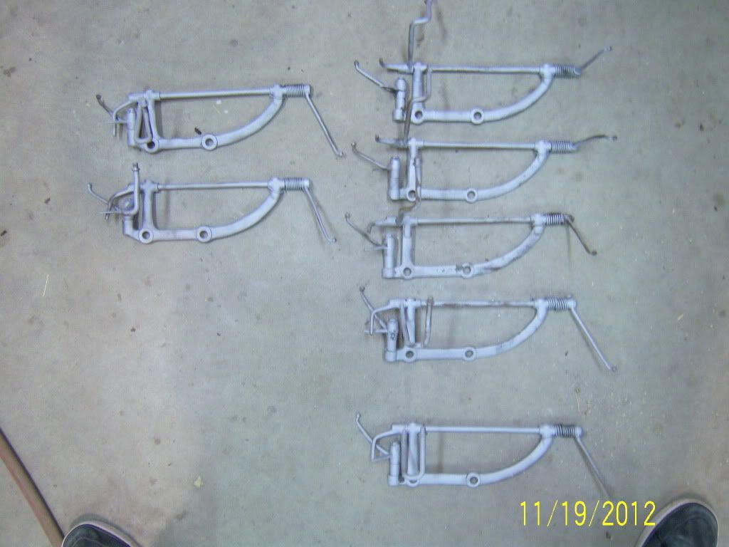
|
|
|
|
|
11-18-2012, 07:55 PM
|
#61 |
|
Senior Member

Join Date: May 2010
Location: new britain,ct 06052
Posts: 9,390
|
Wow ! ! ! ! 60 postings on a part we aren't sure ever existed The tenacity of the gentlemen on the FordBarn is a good thing.
Paul in CT |
|
|
|
|
11-18-2012, 09:14 PM
|
#62 |
|
Senior Member
Join Date: May 2010
Location: Parksville B.C. Canada
Posts: 880
|
Below each oiler hole, below the shaft, are 2 bulges.
I think someone indicated there's an oil saturated wick inside each bulge? #1 question... is there some passageway for freshly applied oil to reach this wick...or is this an early forerunner of permanent/one time lubrication? #2 another thing... of my shamefully small stash of only 6 throttle assemblies, two have the flat bottom. Quite a few more pics have surfaced with this flat bottom unit...suggesting there must be thousands of them out there. Is there some logical reason they didn't illustrate the flat bottom unit in the judging standards? .....Or....could it be the 2 dead guys responsible for the #2 ribbed assembly pic. actually meant to put in a flat bottom pic? |
|
|
|
| Sponsored Links (Register now to hide all advertisements) |
|
|
|
11-19-2012, 12:37 AM
|
#63 | |||
|
Senior Member
Join Date: May 2010
Posts: 3,099
|
This is a "work in progress" for sure! It has taken a few unexpected turns. Keep in mind I had NO familiarity with the earlier versions (as I had no need) until Rusty opened this can of worms
 . Just kidding Rusty. I saw details presented in a few photos that provided necessary details to build on. . Just kidding Rusty. I saw details presented in a few photos that provided necessary details to build on.Quote:
Dudley cleaned and tore his down providing photos and saying the wick was BELOW the shaft but his didn't have an oil cup. His description along with the pic showing the bulges made me see them as bored oil wells. Quote:
Quote:
__________________
http://www.abarnyard.com/ |
|||
|
|
|
|
11-22-2012, 10:35 PM
|
#64 |
|
Senior Member
Join Date: May 2010
Location: Mpls, MN
Posts: 27,582
|
These threads disappear much too quickly. I had to look at the bottom of page 4 for this one. I was looking through the Service Bulletins to see what was pictured for throttle linkage and the first one is one page 337 (April, 1929) and shows the third style listed in the Judging Standards.
There is an original June 1928 Tudor in our club and I'll have to check it out the next time I get a chance, to see which style linkage it has. |
|
|
|
|
11-24-2012, 01:15 PM
|
#65 | |
|
Senior Member
Join Date: May 2010
Location: Fresno, Ca.
Posts: 3,636
|
Quote:
range from 6-1-28 thru(say) 12-31-28. Any help out there? |
|
|
|
|
|
11-25-2012, 01:16 PM
|
#66 |
|
BANNED
Join Date: May 2010
Location: Walla Walla, Washington USA
Posts: 6,066
|
Sponsored Links (Register now to hide all advertisements)
Pluck |
|
|
|
|
11-26-2012, 08:10 PM
|
#67 |
|
Senior Member
Join Date: May 2010
Location: Fresno, Ca.
Posts: 3,636
|
Under "Engineering Information"....for the "Throttle Assembly", I have at least one
or two questions.. Dates, 10-24-1927 and 12-10-1927...that should be Type 1 Date, 6-12-28 is the next date...is that a Type 2? Dates, 9-12-28 and 10-16-28 follow...next or revised Types? Is "Engineering Information", new prints, revisions, tooling or machining change,foundry change...or just a note/letter? |
|
|
|
|
11-26-2012, 09:44 PM
|
#68 | |
|
Senior Member
Join Date: May 2010
Posts: 3,099
|
Quote:
It appears you're looking at the assembly drawings only which I suspect some are missing including one dated 4/5/28. There are at least 149 different related drawings on file and 15 of the bracket alone. Without looking at them and/or the engineering releases it tough to determine much definitively. Some change can be as minor as the notation changing the spec on heat treatment. Others can be changing the +/- tolerance on a hole size or radius. Finally, it's possible the 6/12/28 date you mentioned is simply a "catch-up" on the records including a change in the bracket itself which was recorded 5/8/28, except I'd really expect it to carry the corresponding engineering release number which it doesn't. I hope to be able to post some things in a couple days (when the rain hits) that will help or prompt folks to look at there cars for some real life feedback.
__________________
http://www.abarnyard.com/ Last edited by Marco Tahtaras; 11-26-2012 at 09:59 PM. |
|
|
|
|
|
11-28-2012, 10:14 AM
|
#69 |
|
Senior Member
Join Date: May 2010
Location: Fresno, Ca.
Posts: 3,636
|
Ya..well I thought 21 "lines" was a little short! I didn't think they would have had
there " poop in a neat pile",....there would have had more prints/revisions Guess I'm looking in the wrong place? |
|
|
|
|
12-07-2012, 03:38 PM
|
#70 |
|
Junior Member
Join Date: Nov 2011
Location: Sanger,Ca
Posts: 1
|
ttt
|
|
|
|
|
12-08-2012, 08:15 AM
|
#71 |
|
Senior Member

Join Date: Aug 2012
Location: South East Wisconsin
Posts: 1,279
|
I just checked my stash and can find none of the second ribbed style of throttle assembly. I have one of the early square ribbed style, and the rest later ones, like everyone else. Rod is right. Someone from JS needs to show us a real life example of the second ribbed style. mike
|
|
|
|
|
01-29-2013, 03:39 PM
|
#72 |
|
Senior Member
Join Date: May 2010
Location: Fresno, Ca.
Posts: 3,636
|
Well...for the 3rd year in a row, I looked at the Turlock swap-meet(about 40 acres worth), for the 2nd style. Slim Pickens....and I don't mean the actor, looked at about
60-70 assembles. Any news or update? |
|
|
|
|
04-07-2015, 10:26 AM
|
#73 | |
|
Senior Member
Join Date: May 2010
Location: Fresno, Ca.
Posts: 3,636
|
Quote:
I look every day on ebay and when I'm out "junking" ! If,..your tired of this or need a break for a bit, I have a few other odd ball things too look up.....which should be fun. Thanks again to you and the guy's for all your hard work ! Dudley |
|
|
|
|
|
04-23-2020, 06:20 AM
|
#74 |
|
BANNED
Join Date: May 2010
Location: Walla Walla, Washington USA
Posts: 6,066
|
WOW...That was some reading and excellent research by all involved on the throttle assembly.
So it has been 5-6 years now since this post/thread has appeared, what then has changed in the timeline of these assemblies date wise? If #2 in the Standards is out (I presume it is) then #3 becomes #2 with a starting date of June 1928 with or without oil cups? Has the Judging Standards committee's (MARC and MAFCA) addressed this subject? OR has it gone by the wayside? Yes they changed the Standards...See the 2016 Revision! Thanks. Pluck Last edited by Steve Plucker; 04-23-2020 at 10:02 PM. |
|
|
|
|
«
Previous Thread
|
Next Thread
»
 Linear Mode

|
|

| Sponsored Links (Register now to hide all advertisements) |
|
|
All times are GMT -5. The time now is 11:12 PM.