|
|||||||


| Sponsored Links (Register now to hide all advertisements) |
|
|
 |

|
Thread Tools | Display Modes |
 11-08-2011, 07:29 AM
|
#21 |
|
Senior Member

Join Date: May 2010
Location: Connecticut
Posts: 220
|
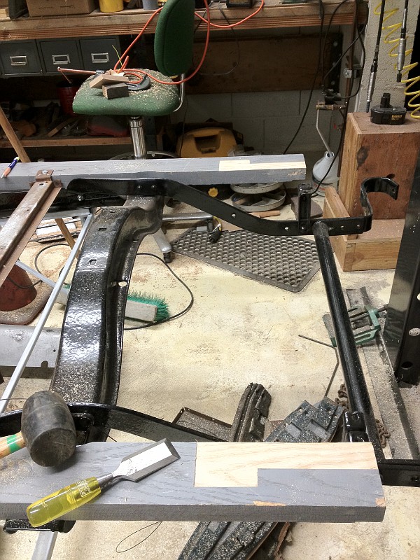
This picture of an original 68-B fixed seat front seat riser was taken by my dad in the late 70's when he was restoring his Cabriolet. He tended to save everything but I can't find the remains of the original today. The riser to the left is one he made from scratch and may very well have the correct angles for the end pieces transposed from the original.

__________________
E30 68-B Cabriolet
|

|

|
|
11-10-2011, 09:00 PM
|
#22 |
|
Senior Member
Join Date: Aug 2011
Location: Millbrae, CA
Posts: 504
|
making progress but time to fill a couple big tail light holes in the back panel before I go any further
 With the cowl in place, I am looking at the alignment of the bottom reveal with the door bottom sheet metal, original and new. 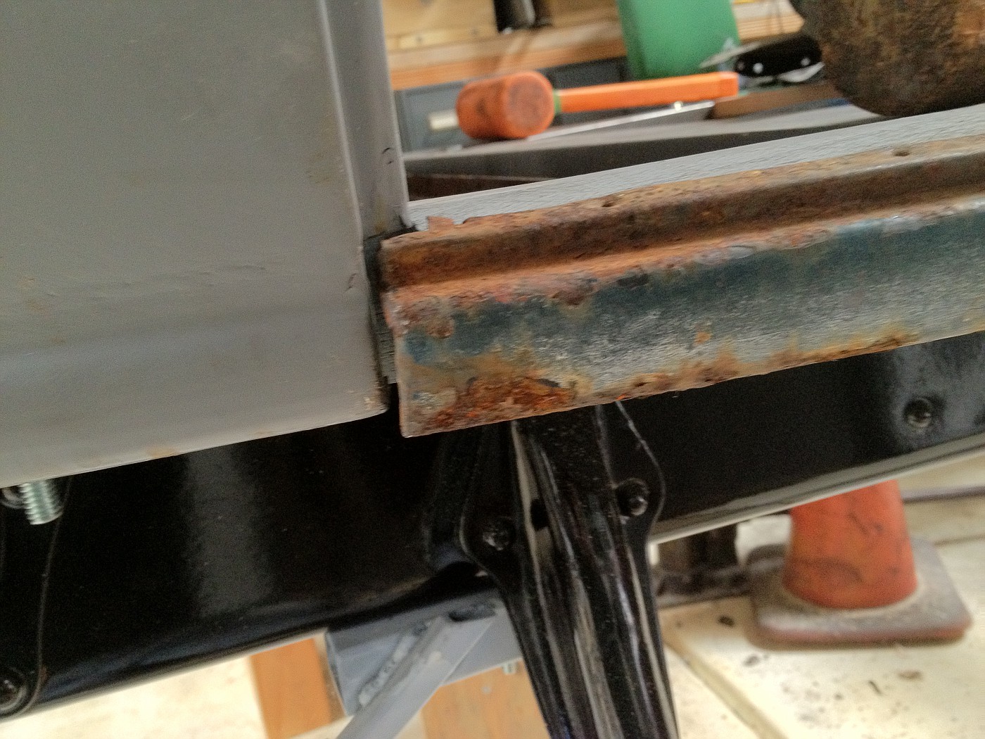 cowl reveal looks a bit short 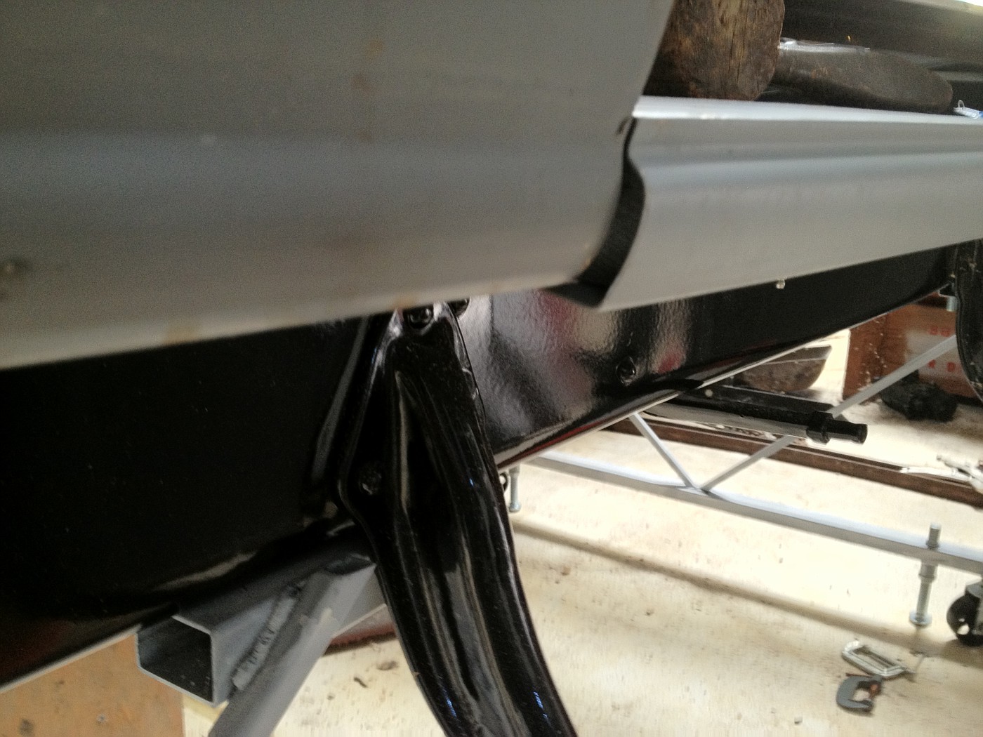 compared to new metal it still looks short; but the new metal shape is looking too angular at the bottom. My cowl bottoms were patched many years ago and they appear to be about 1/8 to 3/16" too thin a reveal at the bottom rear. The front is original sheet metal. While I am not doing a "points" restoration I want to do as good as I can within limits of my abilities. My question is: how perfect were fits on original Briggs bodies? I am planning to rework both the cowl bottom and the shaped pieces under the doors, but do not know how perfect I should try to get them. |
|
|
|
| Sponsored Links (Register now to hide all advertisements) |
|
|
|
11-10-2011, 09:29 PM
|
#23 |
|
Senior Member
Join Date: May 2010
Location: Connecticut
Posts: 220
|
A friend of mine has a 68-B and this his how his drivers side bead below the door meets the cowl. The outside of the bead lines up somewhat with the cowl bead and the back edge of the bead lines up with the cowl recess for the door.

__________________
E30 68-B Cabriolet
|
|
|
|
|
12-07-2011, 12:33 AM
|
#24 |
|
Senior Member
Join Date: Aug 2011
Location: Millbrae, CA
Posts: 504
|
 I cut in the B pillar a few days ago. I marked the door edge profile on the sill to confirm the proper location. |
|
|
|
|
12-07-2011, 07:47 AM
|
#25 |
|
Senior Member
Join Date: May 2010
Location: South East NJ
Posts: 3,398
|
I see the rumble seat pan you have the front corners cut and bent up to clear the wood.
Are you aware that they were just cut out? When I get a chance I will look for my pictures of what the corners look like off an original. I hope you guys realize a lot of pictures already exist over on Bob's cabriolet website. Though these are some nice pictures for people working with the repro parts. |
|
|
|
|
12-07-2011, 04:40 PM
|
#26 |
|
Senior Member
Join Date: Aug 2011
Location: Millbrae, CA
Posts: 504
|
Sponsored Links (Register now to hide all advertisements)
I knew I was not done with the corner, so I did not cut and toss, not knowing how to do it right. I generally go slow enough to not make irretrievable errors. I have spent time looking at Bob's cabriolet website, but there are so many photos there and the site's organization is not suited for quickly finding the info I am looking for. I just need to spend a lot of time looking through a lot of info each time I go there. It is nevertheless a great resource. I know it will be very helpful when I get to doing the upholstery. I will look some more for a photo of the corner detail. I am guessing it is the same as the edge of the rumble seat floor pan as it dips down between the sill rails just behind the front seat riser. My B pillars need to be shaved in the middle outside to properly match the outside curvature of the doors. ...about 1/16" max. That needs to be done before I route a vertical notch (about 1/4" by 3/8") in the outside front corner of the pillar to let the front edge of the sheet metal quarter panels sit properly. I have a Bosch planer that is marked in 1/64" increments, but I have not used it to shave curved surfaces before. ...a little experimentation is needed; but first I need to acurately measure and mark the pillars for planing. Using reproduction sheet metal is a challenge as it is generally of such poor quality in not always obvious ways. I am relatively lucky having good original sheet metal for almost all but the floor and rumble seat areas. |
|
|
|
|
01-04-2012, 12:39 AM
|
#27 |
|
Senior Member
Join Date: Aug 2011
Location: Millbrae, CA
Posts: 504
|
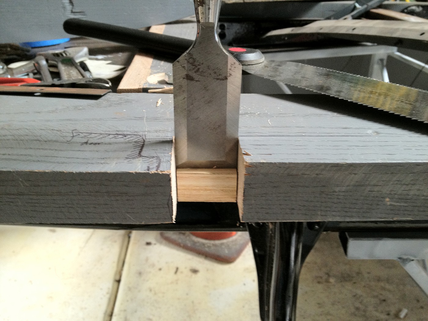
Finally today, I routed the "L" shapes at the back of my main sills
 I just followed the guidance in The Cabrioletter (#114). The article suggested cutting 'about' 1/16" deep, but I cut a little less. The bases of the two pieces that fit on top of the "L" recess are only 0.035" thick, so I went about 0.040-0.45." I have been fitting new wood for the doors, too. 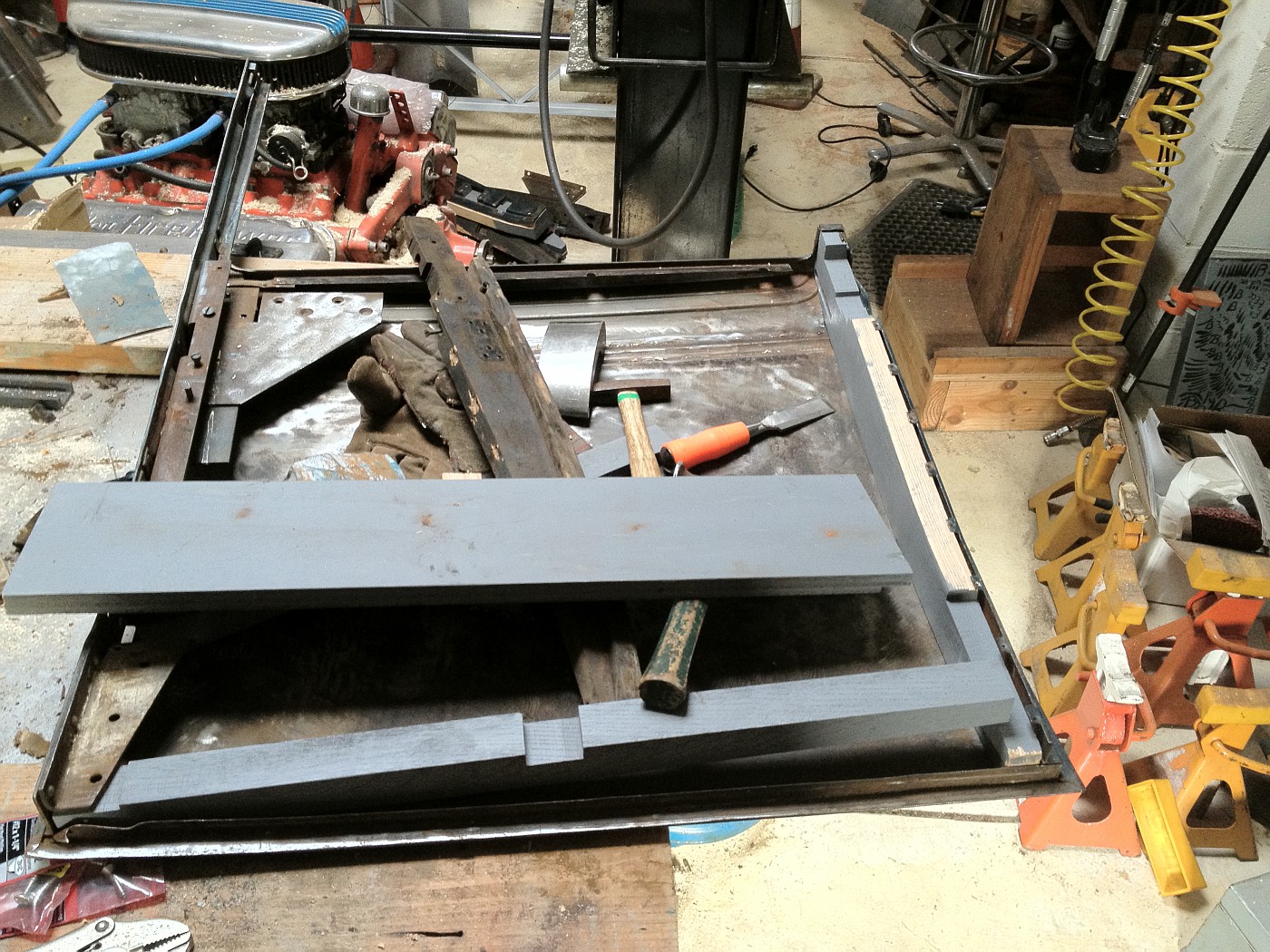 Some of the wood pieces had to be completely re-cut, and others additional thickness had to be added, but most only required a little shaving and the normally expected fitting effort. 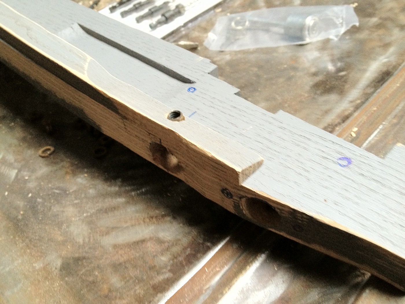 This is the two rear door wood pieces and the photo shows the right door lock hole and with the set screw holder in position, threaded through the two pieces. The piece that fits at the top of the door needed extra work. 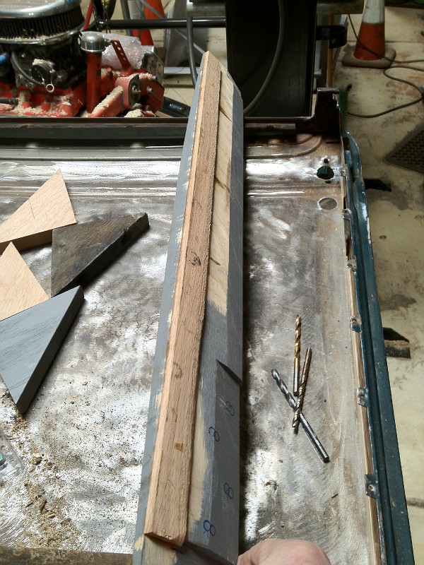 The reproduction piece was nearly 3/16" too thin at its top edge. The unpainted strip was thinned down to proper thickness and glued onto the reproduction piece. The resulting piece looks a bit oddball, but has all needed mating surfaces and will not be seen after door is assembled. As the sheet metal on these Briggs Body doors was originally skinned on top of a wood and metal frame, replacement of just the wood can not be done in the same manner as the door was originally constructed. This top piece is the most difficult to place back into the metal framework. The Cabrioletter suggested using a two piece top piece; but with a little modification, I think it can be installed as a single piece and be stronger than a two piece one would be. I will await final assembly of the door wood until after the door skins have been sand blasted and primed. The sheet metal is amazingly good on these doors. The only patch needed was from a tear/crumpling coming back from the door handle, only about one square inch of metal! 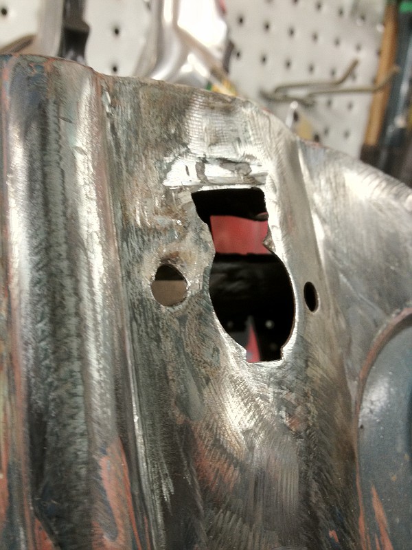
Last edited by Russ B; 01-11-2012 at 02:23 PM. Reason: Correct reference cited |
|
|
|
|
01-25-2012, 10:28 PM
|
#28 |
|
Senior Member
Join Date: Aug 2011
Location: Millbrae, CA
Posts: 504
|
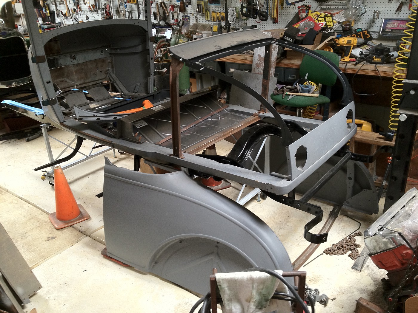
Just adding a few more photos to the thread.
 This shows some of the inside back braces, everything still loose at this time. 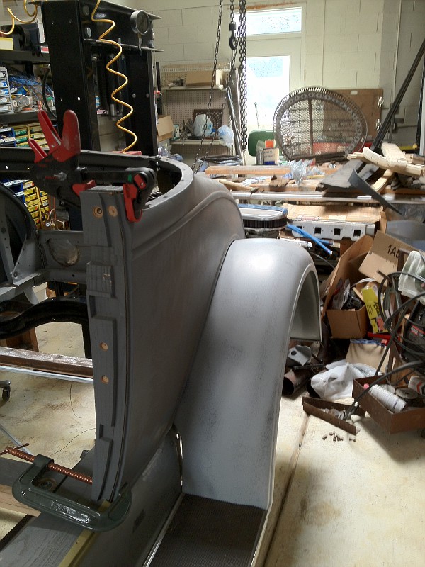 Before I tie anything down, I want to assemble as much as possible to see if there are any obvious fit problems. 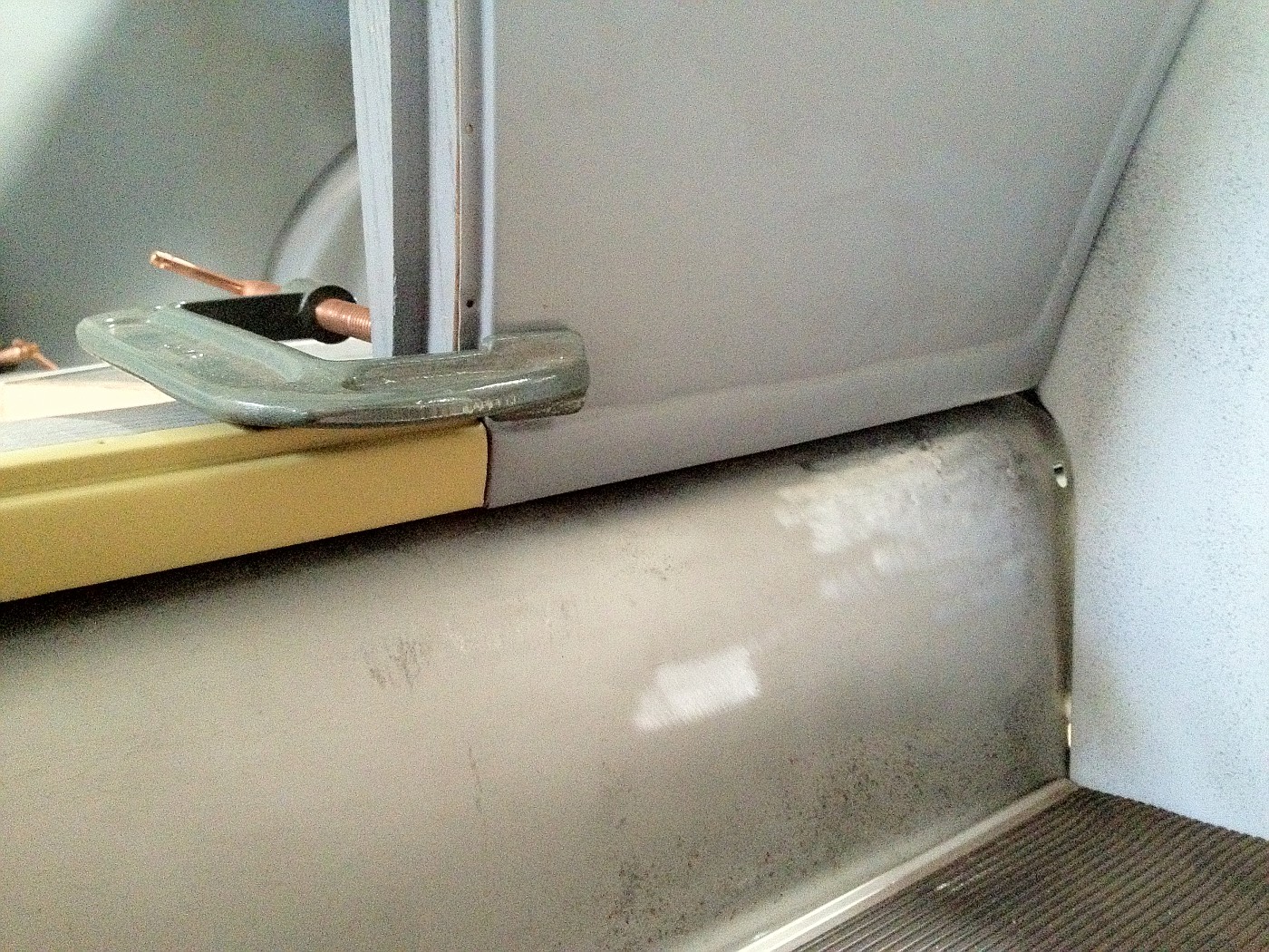 I had to cut an 1/8" off the bottom of my B pillar to get these pieces to line up. 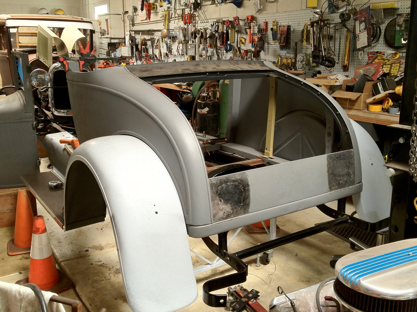 Still a lot of work to make it all fit. As I am using a reproduction rumble/trunk lid, I will try to fit it on soon to see what more needs to be done to get a matching curvature on the back panel. |
|
|
|
|
01-27-2012, 05:41 PM
|
#29 |
|
Senior Member
Join Date: Feb 2011
Location: NNNNNNNNJJJJJJJJJJ
Posts: 6,782
|
Well fellas, was just out in the garage (in the 60's today!) and got the sills on and everything went together like a jigsaw puzzle! Will need help lifting and readjusting the cowl and lifting the back body on, but everything is lining up. The photos you guys sent in were a tremendous help....
I am missing a cross brace or two, but otherwise coming together nice. My seat is adjustable, btw. Wish I knew how to readily upload photos.... |
|
|
|
|
01-27-2012, 08:52 PM
|
#30 | |
|
Senior Member
Join Date: Aug 2011
Location: Millbrae, CA
Posts: 504
|
Quote:
That cowl is heavy. I have been able to move mine short distances by myself, mostly it is stripped, no gas tank, etc. ...but it generally takes a bit of recovery time afterward for my own old body. The body is being built on the frame, which is on a stand. It still will be a challenge when I am ready to go to full assembly. ...and then to paint and reassembly. Photos are not hard to do if you have a photo storage site on line like Fotki.com. I just post from there to here. Last edited by Russ B; 01-27-2012 at 09:48 PM. Reason: Typo |
|
|
|
|

|
01-27-2012, 08:59 PM
|
#31 |
|
Senior Member
Join Date: May 2010
Location: South East NJ
Posts: 3,398
|
From experience,
Since you had to remake the bottoms of the forward braces that go from the sill to the upper cross piece (the yellow ones in your pictures) you may find the doors do not line up top to bottom. I found I could pry these braces up some to get the doors to line up top to bottom. In other words, if it looks like the qtrs are too wide or narrow at the top, then you need to adjust these brackets. I had to make my brackets up from repros and I had to guess at the proper length. That coupled with having to do extensive work on the qtrs. I was shy by a couple of pieces of 18 gauge sheet metal under the braces of getting the doors to fit. |
|
|
|
|
01-27-2012, 10:09 PM
|
#32 | |
|
Senior Member
Join Date: Aug 2011
Location: Millbrae, CA
Posts: 504
|
Quote:
|
|
|
|
|
|
01-27-2012, 11:10 PM
|
#33 |
|
Senior Member
Join Date: May 2010
Posts: 332
|
You are not ready for this yet but be sure to fit the windows and slides to the doors before you think it is ready for final paint. Don't ask why I know.
|
|
|
|
|
01-28-2012, 07:11 AM
|
#34 |
|
Senior Member
Join Date: May 2010
Location: Connecticut
Posts: 220
|
Russ
I've read that article in the Cabrioletter regarding the the "L" shaped recess in the rear of the chassis wood. After putting the rear half of the car together where the original rear brackets are mostly intact, my initial impression is the recess is not needed. I could be wrong but for now I can't see why it is needed as my brackets fit nicely on top of the wood without it. The series including issue #114 in the Cabrioletter has great information for fitting wood in these cars. One area that needs correction and I hope to get an article written this year is the fitting of the set screw for the passenger door lock. It is a small detail but the Cabrioletter in past articles has it wrong. The set screw housing should be inserted through the hole for the door handle and not from the other end. This is how it was done originally and makes for the strongest mount as the set screw housing boss presses against the larger door latch post. I'll post a picture later. Rich
__________________
E30 68-B Cabriolet
|
|
|
|
|
01-28-2012, 07:29 AM
|
#35 |
|
BANNED
Join Date: May 2010
Location: Walla Walla, Washington USA
Posts: 6,066
|
This is a great and interesting thread.
Nice work! Pluck |
|
|
|
|
01-28-2012, 08:02 AM
|
#36 |
|
Senior Member

Join Date: May 2010
Location: Naperville, IL
Posts: 1,387
|
Keep the pictures and dialog coming! I am saving them all for reference to use as I restore the body of my August '29 68A. The chassis is done. Thanks for making the effort. Gar Williams
Last edited by Aerocraft; 01-28-2012 at 08:05 AM. Reason: add photo |
|
|
|
|
01-28-2012, 11:26 AM
|
#37 |
|
Senior Member

Join Date: Jul 2010
Location: Oslo, Norway
Posts: 521
|
Russ, great post ! My cabriolet is a 1930, but I think a lot of the parts are identical, so I am also following your good work with great interest all the way over here in Norway !
|
|
|
|
|
01-28-2012, 03:09 PM
|
#38 | |
|
Senior Member
Join Date: Aug 2011
Location: Millbrae, CA
Posts: 504
|
Quote:
I did make the "L" recess and am still waiting to see if it is needed. I am not far enough along on my fitting to be sure. Briggs factory photos, in the "How To ..." series article on the 68C body show the "L" recess/notch, iirc. I think there is a good chance I will need it in my assembly. My fitting of door wood varied a bit from the Cabrioletter guidance as well. That wonderful guidance is a kind of bible for many of us doing this work, but I think all of us find slight differences or improvements in how we do the assembly. Once done with mine I plan to write something up and send it to Larry for use in the Cabrioletter as additional hints on assembly of the body. One additional thought, soon I will be tieing down my "B" pillars and have some uncertainty about the lower triangle pieces that fit behind them. The guidance in the Cabrioletter has two photos showing the open side of the lower piece facing toward the inside of the body while the upper triangle (turnbuckle) piece has the open side facing toward the outside of the body, #116, see figures "E", "F", and "G". When I disassembled my body many years ago, I scratched an "L" and "R" on my lower pieces indicating the open sides would face to the outside, like the upper pieces do. This seems logical for how I would envision factory, jig based, assembly of the body, they seem to fit properly that way, and that is how I am planning to do mine at this time. However, I think I have seen assembly photos on "Bob's Cabriolet Page(?)" indicating assembly with the top piece open side out and the bottom piece with the open side faced inward. Is one way right and the other way wrong? Thanks again to Ronn for starting this thread. |
|
|
|
|
|
01-29-2012, 08:15 AM
|
#39 |
|
Senior Member

Join Date: May 2010
Posts: 130
|
Russ,
The lower triangle pieces face towards the inside of the car and the uppers face towards the outside. If you look and the lowers you will see that the ends are bent to less than 90 degrees to allow the pieces to fit properly against the sills. There is a left and right side piece; they are not the same. The tops have to face towards the outside to allow for the triple hinge screws to fit correctly. Since I just finished assembly my car (just lacking a top), here is the most important tip I can give you about the B post. Leave the triangle brackets loose! Put one screw on each side and leave it until final assembly. The reason is that there is a lot adjustment to be found in the post when you are setting the door gap, but if you have it all screwed down tight, you will pretty much be stuck wherever you initially set it. As for the "L" shape cutout, I put in the cutout and am glad I did. The cutout allows you to raise or lower the back of the body just enough to affect the door gap. I ended up having to shim the triangle piece at the front of the L while the back was just fine. Better to cut it in and not need it then to need it and have to take the car apart to cut it in. |
|
|
|
|
02-18-2012, 11:56 PM
|
#40 |
|
Senior Member
Join Date: Aug 2011
Location: Millbrae, CA
Posts: 504
|
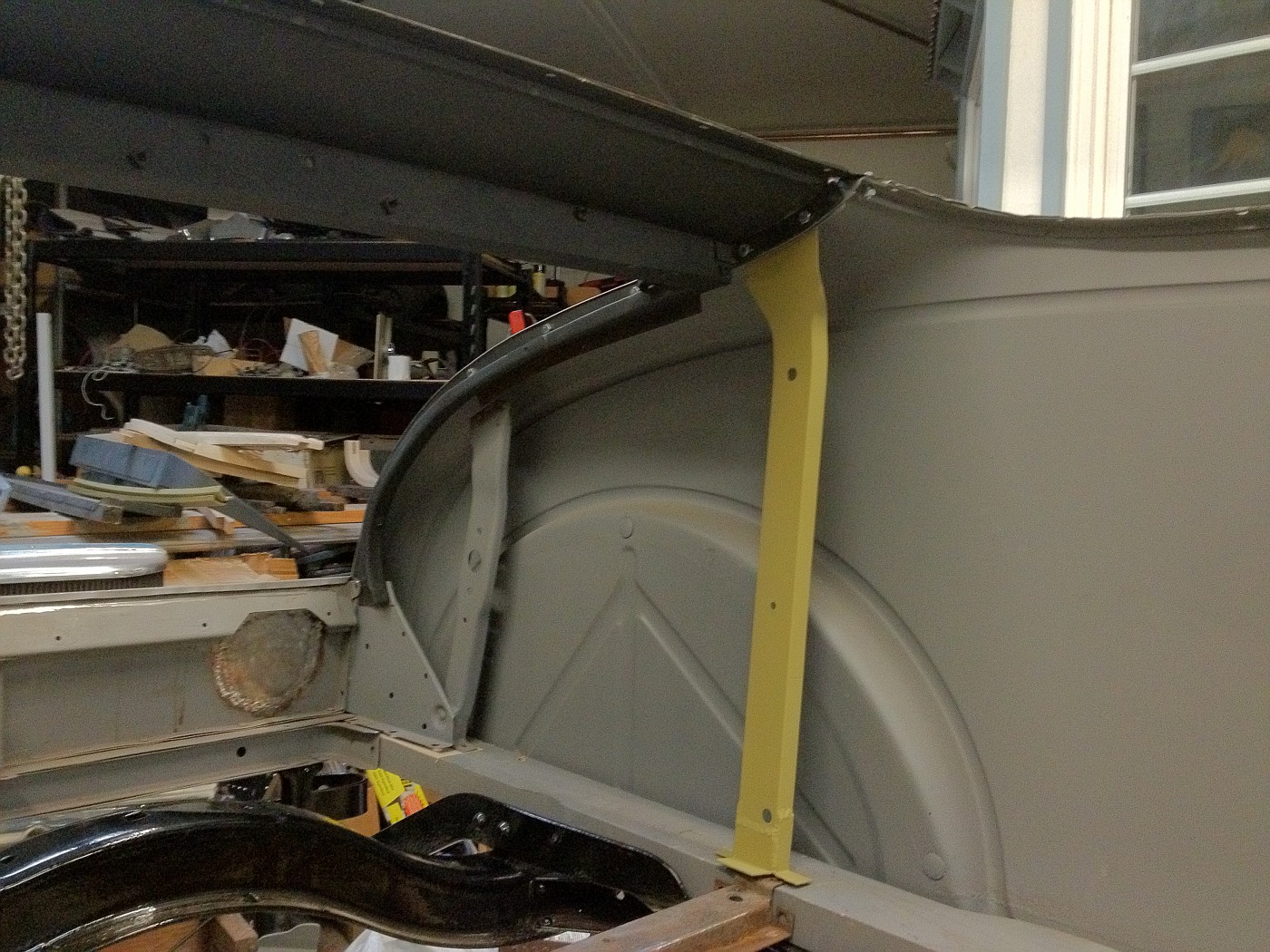
A few more cabriolet assembly photos that may be of help to someone.
The right side quarter panel still a little low compared to the B pillar and the turnbuckle brace behind it. 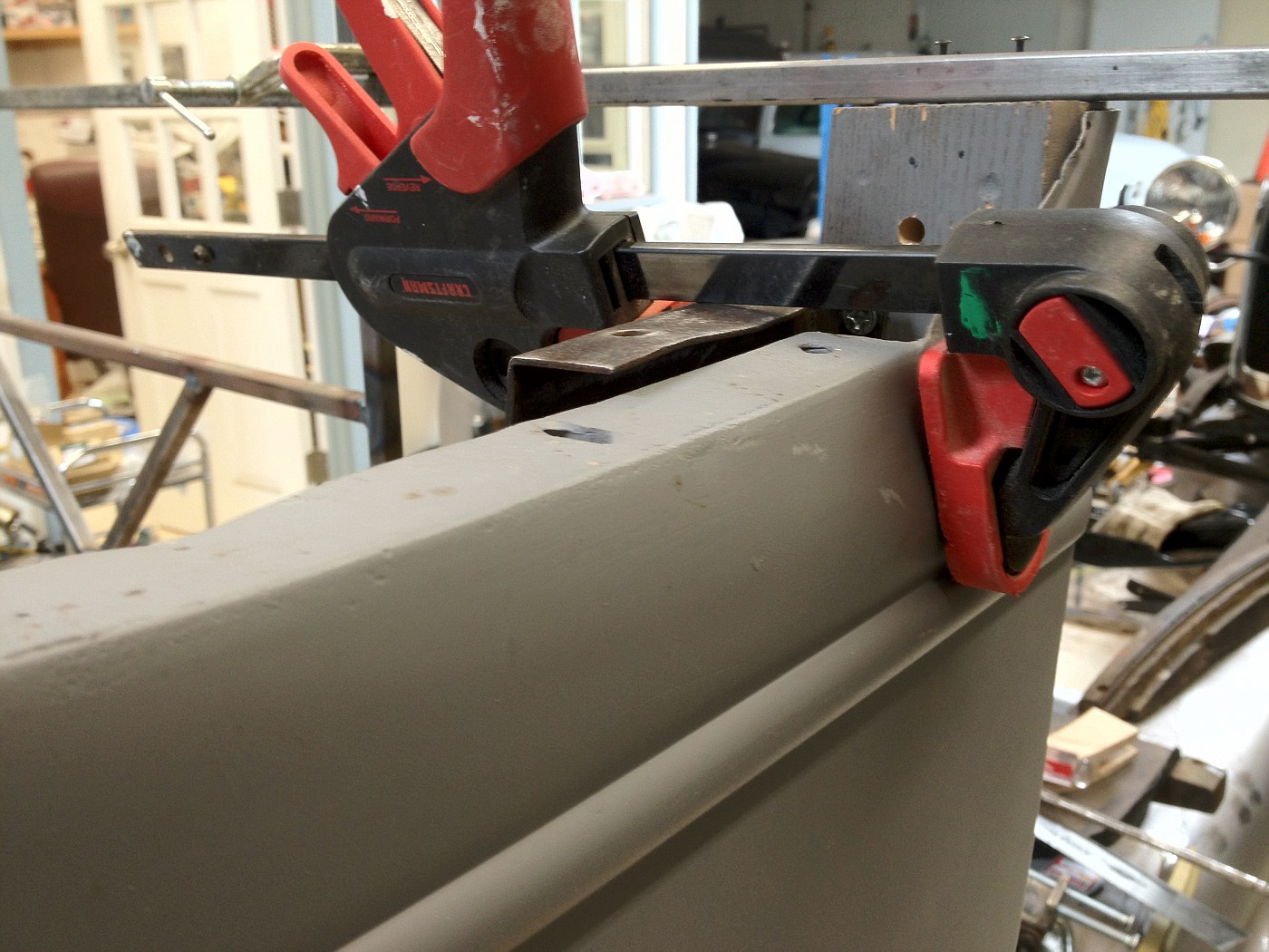 The same as above but looking from the inside. 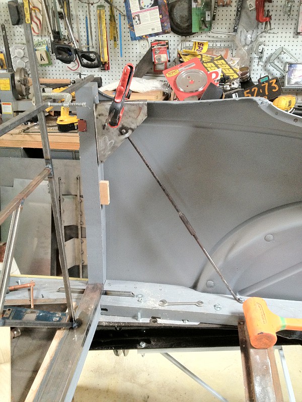 The lower triangle piece (B pillar brace), not installed, but sitting in position, facing inward, as compared to the outward facing upper piece. 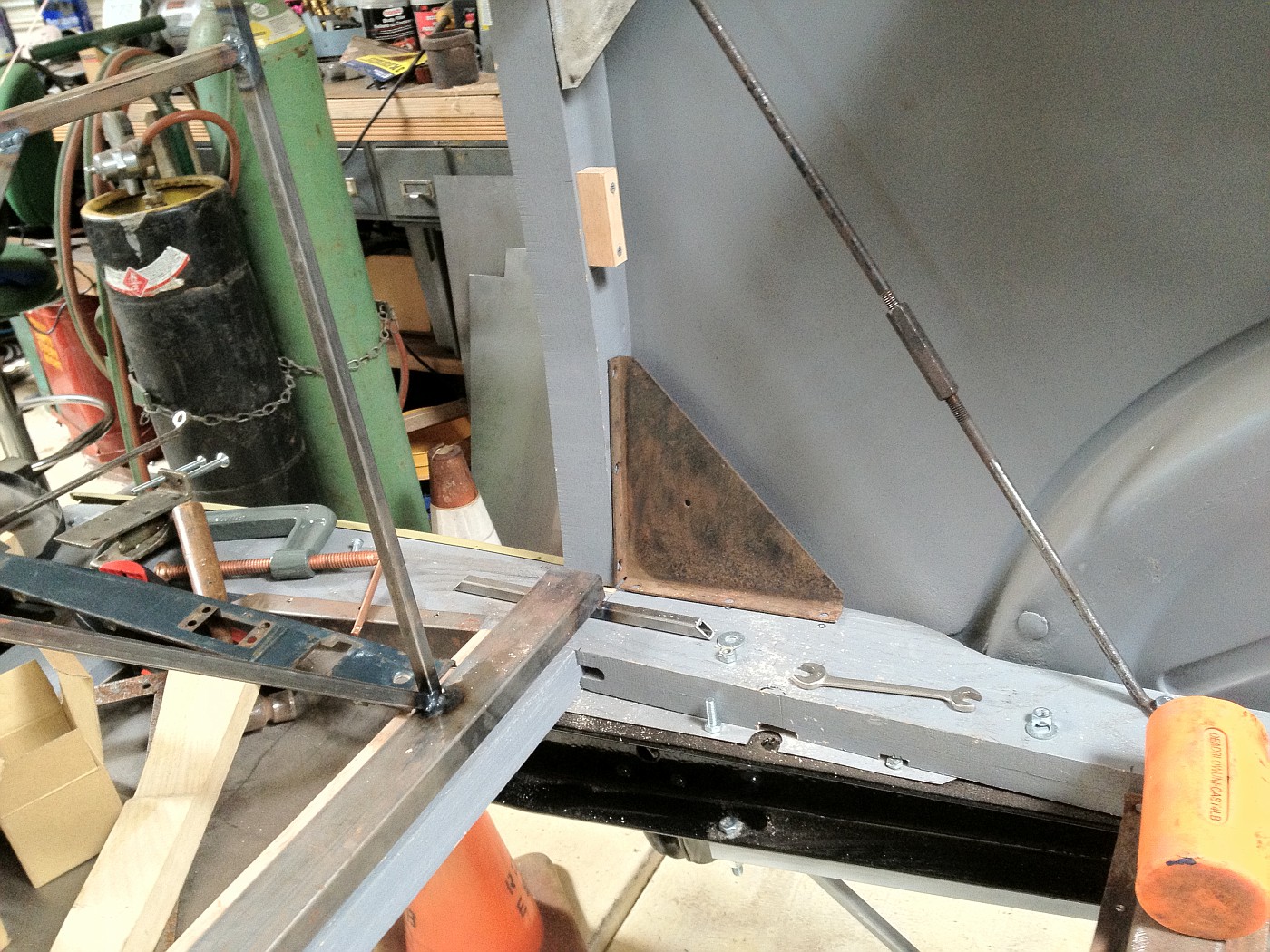 The cover (in red oxide primer) over the latch notch (on the right B pillar). Someone else may have a proper name for this piece. 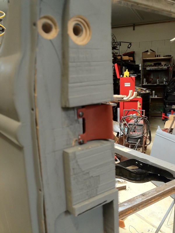 The holes above the cover piece are for mounting the triple hinge assembly. I drilled both at 5/16" though the outer one uses a 1/4" bolt. ...Just thinking it will allow slight adjustability. |
|
|
|
|
«
Previous Thread
|
Next Thread
»
| Thread Tools | |
| Display Modes | |


 Linear Mode

|
|

| Sponsored Links (Register now to hide all advertisements) |
|
|
All times are GMT -5. The time now is 08:40 PM.