|
|
#21 |
|
Senior Member
Join Date: May 2010
Location: Cape Cod
Posts: 1,128
|
|
|
|

|
|
|
#22 | |
|
Senior Member
Join Date: May 2010
Location: Alabama
Posts: 8,099
|
Quote:
Steve S gave the correct and simple answer to your question of how to find the correct polarity of YOUR ammeter on post number 7 . I really don't know what the original ammeter bezel looks like . I do know that many of the repro ammeters are actually 26-27 model T and the model T was negative ground and will require the wires to be reversed to register correctly if used on the model A . This same subject came up just the other day . Too much info complicates and confuses matters. If it cranks and runs good, the coil is probably hooked up correct. There is a tool sold my many venders for checking coil polarity. |
|
|
|

|
| Sponsored Links (Register now to hide all advertisements) |
|
|
|
|
#23 |
|
Senior Member
Join Date: May 2010
Location: Mpls, MN
Posts: 27,582
|
On the Chicagoland MG club's drawing they show both the correct and incorrect coil polarity checked bu using a pencil. Unfortunately they didn't label the pictures "CORRECT" and "INCORRECT". The middle picture is correct. The flare is between the pencil and spark plug when the coil polarity is correct.
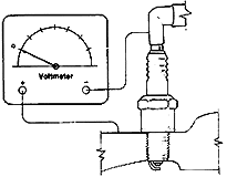
What might get confusing is the point of the flare is towards the coil, so when they say the flare is "away from" one might think this means away from. Never mind the point of the flare, just be sure the flare is between the pencil and plug. Below is a bit from the MG club: "If you are still skeptical about all this, there is a quick way to check directly which way the current is flowing in the high tension circuit. Disconnect a spark wire from a spark plug (or the coil wire from the distributor cap). Hold this HT wire near a grounding point (or near the connector end of a spark plug), and position the tip of a graphite pencil in between. When you crank the engine (no need to start or run) you can observe the resulting spark jump between wire and pencil, and between pencil and ground (or spark plug). A flare (hard to see) toward the plug (or ground) shows correct polarity while a flare toward the coil shows reversed polarity. If the flare goes toward the coil, just switch the primary wires on the coil and make note of the connections for future reference.   Can't see the flare? Not sure yet? You can also check spark polarity using an analog (moving needle) volt meter. Hook up a voltmeter with the negative lead to the plug terminal and the positive lead to the block. Set the meter on the highest volt range. Crank the engine over (no need to start it), and you should see an upward swing of the voltmeter needle (don't be concerned with taking a reading). If the needle swings down off the scale, your coil is hooked up wrong. To correct it reverse coil primary leads. Do not worry about the coil markings, but make note of them for future reference." Can't see the flare? Not sure yet? You can also check spark polarity using an analog (moving needle) volt meter. Hook up a voltmeter with the negative lead to the plug terminal and the positive lead to the block. Set the meter on the highest volt range. Crank the engine over (no need to start it), and you should see an upward swing of the voltmeter needle (don't be concerned with taking a reading). If the needle swings down off the scale, your coil is hooked up wrong. To correct it reverse coil primary leads. Do not worry about the coil markings, but make note of them for future reference."
|
|
|

|
|
|
#24 | |
|
Senior Member
Join Date: May 2010
Posts: 3,099
|
Quote:
This happened to coincide with the transition to the straight poll coil and introduction of the new 1930 passenger models. The new coils had the internals rotated 180 degrees thereby reversing the polarity. This allowed Ford to continue routing the wires straight up from the terminal box to the coil instead of crossing the wires. A number of the final slant pole coils were produced with the revised polarity.
__________________
http://www.abarnyard.com/ Last edited by Marco Tahtaras; 02-10-2013 at 10:05 PM. |
|
|
|

|
|
|
#25 |
|
Senior Member
Join Date: May 2010
Location: Cape Cod
Posts: 1,128
|
Marco,
Thanks for the additional information. Marc |
|
|

|
 |
«
Previous Thread
|
Next Thread
»
|
|
| Sponsored Links (Register now to hide all advertisements) |
|
|
All times are GMT -5. The time now is 01:46 AM.


 simple guy with (what i had hoped) simple questions .... thanks for your patience!!

 Linear Mode

