|
|||||||


| Sponsored Links (Register now to hide all advertisements) |
|
|
 |

|
Thread Tools | Display Modes |
 04-18-2011, 11:50 AM
|
#1 |
|
Senior Member

Join Date: May 2010
Location: Mpls, MN
Posts: 27,582
|
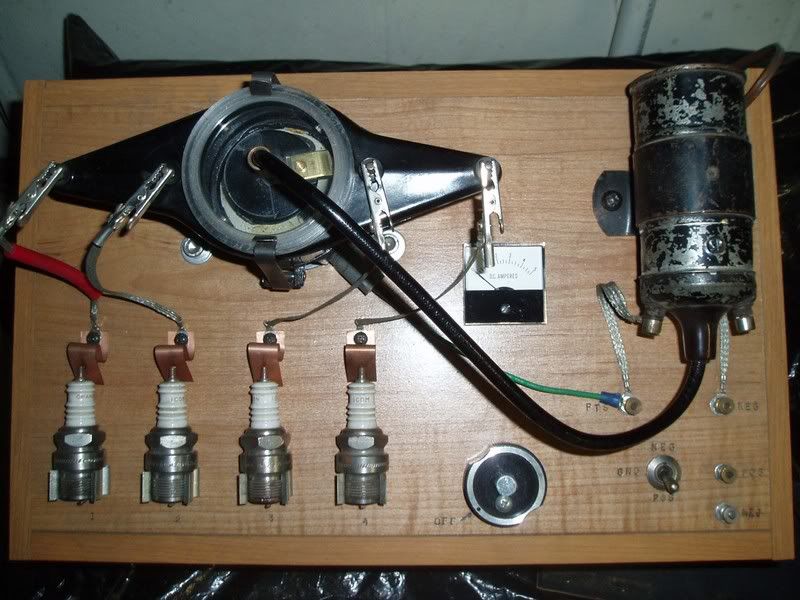 As Paul Harvey would say "Here's a Strange". I made this Model A ignition simulator several years ago and used it during my demonstration in Chicago a few weeks ago. Last night I was playing with it and #4 all of a sudden had no spark at the plug and no spark at the rotor to cap gap. I have a clear cap, so I can watch the rotor and spark. The other 3 kept firing normal, but for several seconds #4 had no spark. I also noticed some sparking by the condenser on the back side of the distributor. By the time I tried to check the condenser, the sparking back there quit and #4 sparked as normal again. Any loose connection or dirty points should have given random sparking problems, and not just #4. A short in the distributor cap should have still shown a spark at the rotor to cap gap for #4. I'm at a loss as to why this problem happened, and so far I can't make it happen again. Last edited by Tom Wesenberg; 04-18-2011 at 12:10 PM. |

|

|
|
04-18-2011, 04:53 PM
|
#2 |
|
Senior Member

Join Date: May 2010
Location: new britain,ct 06052
Posts: 9,428
|
HA HA HA HA! Good one !
Paul in CT |
|
|
|
| Sponsored Links (Register now to hide all advertisements) |
|
|
|
04-18-2011, 05:02 PM
|
#3 |
|
Senior Member
Join Date: May 2010
Location: Crete, Illinois
Posts: 306
|
Tom,, just wondering if the screw to the condensor is tight and it has the proper insulation. Jon
|
|
|
|
|
04-18-2011, 05:07 PM
|
#4 | |
|
Senior Member
Join Date: May 2010
Location: Mpls, MN
Posts: 27,582
|
Quote:
|
|
|
|
|

|
04-18-2011, 05:21 PM
|
#5 |
|
Senior Member
Join Date: May 2010
Location: Cen~Col - Central Highlands
Posts: 2,757
|
Tom is the ground terminal soldered on the condenser?
Could the gap be wider than the other 3 gaps between the rotor and #4 terminal on the body? 1243 |
|
|
|
|
04-18-2011, 05:45 PM
|
#6 | |
|
Senior Member
Join Date: May 2010
Location: Mpls, MN
Posts: 27,582
|
Sponsored Links (Register now to hide all advertisements)
Quote:

|
|
|
|
|
|
04-18-2011, 06:19 PM
|
#7 |
|
Senior Member

Join Date: May 2010
Location: Creston Canada BC
Posts: 609
|
Hi Tom could you post a picture from the rear ??? Like to copy the idee
Thanks, Gerard |
|
|
|
|
04-18-2011, 09:16 PM
|
#8 |
|
Junior Member

Join Date: May 2010
Location: Andover, Minnesota
Posts: 7
|
Did you check the flux capasiter?
|
|
|
|
|
04-19-2011, 05:41 AM
|
#9 | |
|
Senior Member
Join Date: May 2010
Location: Mpls, MN
Posts: 27,582
|
Quote:
I made a cam to work the variable speed control and the microswitch used to turn on the power to the coil. I made the coil power turn on a bit before the drive motor power turns on. This way I can check the amp draw of the coil when the points are closed. Also, this way I can see exactly when the points open by the drop on the amp meter. I use this to check the accuracy of new points cams when I install the dial indicator and degree wheel, as seen stored inside the case in one of the pictures. You can also see the DPDT switch I used to switch the coil polarity from positive ground to negative ground. This comes in handy when switching between 28-9 coils and 30-1 coils. It also comes in handy when using a pencil lead to demonstrate coil polarity checks. |
|
|
|
|
|
04-19-2011, 07:48 AM
|
#10 |
|
Senior Member

Join Date: Jul 2010
Location: Pennsylvania
Posts: 1,251
|
Something was causing the primary circuit to short out whenever a certain point on the distributor shaft passed a fixed point in the distributor. What do you have grounding the points to the lower plate, the standard wire or the wireless plate? I've sometimes seen where the little shoe that screws onto the points that makes contact with the lower plate has very little clearance against the upper plate. Maybe the cam has one lobe slightly higher than the rest, and this caused a pulsation that began grounding out that shoe?
|
|
|
|
|
04-19-2011, 09:28 AM
|
#11 |
|
Senior Member
Join Date: May 2010
Location: Mpls, MN
Posts: 27,582
|
Will,
I never would use a wireless plate on my own distributor and only use original plates. I have a spool of very fine stranded wire (167 strands) and rebuild my own wire using original terminals. The cam has been checked and is within .0005" on each lobe. Wish I could make it miss again on number 4 only, so I could see what happened. |
|
|
|
|
04-19-2011, 02:21 PM
|
#12 |
|
Senior Member
Join Date: May 2010
Location: Mpls, MN
Posts: 27,582
|
 I've had some requests for more pictures, so I've decided to post 6 more pictures here. Notice the wires to the coil primary terminals cross each other. That's because I first built this machine using a coil with the negative post on the other side. Since my cabinet was marked already I had to cross the wires to keep all the markings correct when I used my slant pole coil. The red plastic sleeve on #1 is needed when I connect the inductive pickup on my scope. I made the cabinet out of some old sheving I pulled out of someone's trash can. I was riding my bike when I spotted some nice looking boards and figured even though the shelf unit was broken, the shelves would be good for something.  Here you can see I use a clothespin with a screw to create a 1/2" spark, and hold the pencil lead in the spark path to demonstrate coil polarity.  Here you can see how the dial indicator and degree wheel are safely stored away when not in use. I cut a wood spool in half and use it to store spare drive belts (long O rings). This way if the drive belt breaks, I can just slip on a new one with no down time. 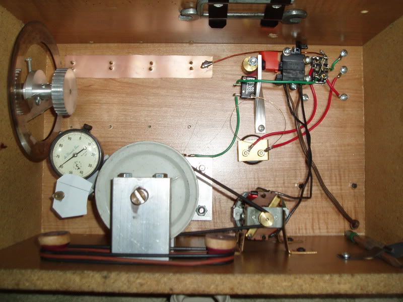 This is an overall view of the bottom showing the clips to hold an Allen wrench, used to tighten the distributor set screw, and a 1/2" open end wrench, used to mount the dial indicator. I also have the pencil clipped in place.  Here you can see the cam I made to operate the lever which turns on the microswitch first to feed power to the coil, then turns on the variable speed switch to power the motor. The thin copper wire is a shunt I had to make for the 5 amp guage, which is used to check the coil draw. 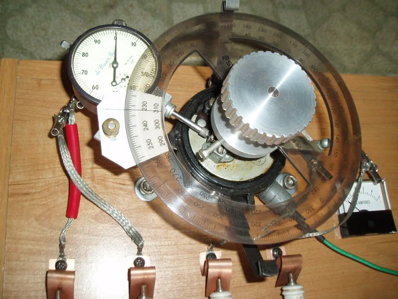 Here you can see the dial indicator mounted as well as the degree wheel, which I use to check the accuracy of cams. The most important cam check for an even firing engine is that each lobe opens the points exactly 90* apart. For the degree wheel to measure accurately I had to make sure it was exactly centered on the aluminum mount I made for it. By turning on the power to the coil I can read the 4 amps it draws, then as soon as the meter goes to zero I read the degree wheel and go to the next lobe and read when the meter goes to zero again. Hopefully it will be exactly 90* from the previous lobe. By reading when the points close, a 4 amp reading, and when the points open, a 0 reading, I can figure the dwell, which is the time in degrees that the points are closed. Last edited by Tom Wesenberg; 04-19-2011 at 02:57 PM. |
|
|
|
|
04-19-2011, 03:44 PM
|
#13 |
|
Senior Member

Join Date: May 2010
Location: Wakarusa, IN
Posts: 932
|
Tom, You are in luck, the Hoosier A Ford Club has a membership position open. Why don't you move over her and join. And I promise we will tolerate your tech presentations and ideas. I like the box.
__________________
http://MODELABASICS.com/ How Things Work on a Model "A" Ford Fordbarners, Feel free to use the pictures on my site to answer questions and create tutorials/tech articles. Last edited by 30ccpickup; 04-19-2011 at 03:53 PM. |
|
|
|
|
04-19-2011, 05:24 PM
|
#14 | |
|
Senior Member
Join Date: May 2010
Location: Mpls, MN
Posts: 27,582
|
Quote:

|
|
|
|
|
|
04-19-2011, 05:43 PM
|
#15 |
|
Senior Member
Join Date: May 2010
Location: Mpls, MN
Posts: 27,582
|
OH GREAT! Now we have another mystery. Vince was the first to reply and now it doesn't show up. What happened to Vince's reply?
|
|
|
|
|
04-19-2011, 05:58 PM
|
#16 | |
|
Senior Member

Join Date: May 2010
Location: Quincy CA
Posts: 752
|
Quote:
I thought his comment was very funny. Joe
__________________
1929 Tudor since 1962 Feather River A's |
|
|
|
|
|
04-19-2011, 06:20 PM
|
#17 | |
|
Senior Member
Join Date: May 2010
Location: Mpls, MN
Posts: 27,582
|
Quote:
|
|
|
|
|
|
04-19-2011, 06:53 PM
|
#18 |
|
Senior Member
Join Date: May 2010
Location: Hendersonville TN
Posts: 180
|
Tom;
I spent last Friday, Sat, and Sunday with a friend who bought the old Lucerne plant in Bolivar Tenn. after it went down. He has 100,s of thousands of powertool trigger switches laying around and keeps giving me hand fulls, I keep putting them back. He and I have no idea what they fit, they are surplus to him, I have no need for more neat stuff. If you or others need any of these, I can have him send me a few of each model he can find in thousands of boxes and I can forward them for the cost of the postage only. He has a completely differant product and this stuff is just in the way.
__________________
Steve - Santa Rosa |
|
|
|
|
04-19-2011, 08:36 PM
|
#19 |
|
Senior Member

Join Date: May 2010
Location: Reseda, Calif.
Posts: 2,191
|
Tom, years ago, when i was alot younger, i use to watch a television show called "Mr. Wizard".. I always liked to see what he would come up with next. And for some reason i see a you as a Mr. Wizard. Have you thought about a tv show? Great learning tool you made there and great pics as well. I always enjoy your post. Keep it up. Mark.
|
|
|
|
|
04-19-2011, 08:54 PM
|
#20 |
|
Senior Member
Join Date: May 2010
Location: Mpls, MN
Posts: 27,582
|
Thanks Mark, wish I could get paid like the guys on TV.
Steve, I bought this Lucerne variable speed switch at the local surplus store for $2.50 about 8 years ago. Guess I now know where they bought the box full of them. I also bought one to replace the bad switch in my Milwaukee drill. |
|
|
|
|
«
Previous Thread
|
Next Thread
»
 Linear Mode

|
|

| Sponsored Links (Register now to hide all advertisements) |
|
|
All times are GMT -5. The time now is 01:24 PM.