Here we go. If all goes well I should end up with thumbnail pictures that you then click to have the full size picture come up. Most of the pictures have been collected on the Ford Barn.
Here is the 221-239-255 cube flathead block story with pictures, to the best of my knowledge and ability to collect pictures so far.
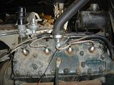
In the beginning of this story it is 1931 and Chevrolet has a 6 cylinder car. Henry Ford had to upstage them. Henry had a crash program going to develop an 8 cylinder motor, but it was not developed enough to put in production. Henry gave the order to start production of the improved 4 cylinder car for 1932, the model B. Apparently as Henry walked past the newly started production line turning out the shiny new 1932 4 cylinder Fords he made the decision to shut the line down and introduce the V8! Ford dealers were without cars for months. Ford Motor Company knew the first V8s were so bad that the first 1500 were not allowed to be sold to the public, they were for static display only and were supposed to be returned to Ford for engine swaps before being sold. And so, into the turbulent under developed world of prototype motors, the V8 Ford was introduced. The number of production changes to engine design in 1932 was phenomenal. A proper discussion of 1932 Ford V8 motors would include as many pictures, or more, as I have in this history discussion. Maybe Dave Cole or David Rehor know all of the changes made in 1932, but I sure don't. And so, if you visit the Henry Ford Museum you can see production V8 number 1, 18-1 itself. This engine was actually prototype motor number 243, but they had to start somewhere. The very early 32 motors feature some unique features, such as bolt on steady rod brackets and a block mounted dip stick. These features can be seen in this picture of 18-1:
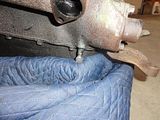
Early in production the oil dip stick was relocated to the oil pan and the block castings were changed to locate the steady rods in the bell housing casting. The 1932 V8 engines features a 3 1/16 bore by a 3 ¾ stroke for 221 cubic inches. The main bearings were 1.998 to 1.999 inches and the rod bearings were 1.998 to 1.999 inches. There was no provision for crankcase ventilation. The oil pan rail had four freeze plugs, two per side. The block featured drain petcocks pointed straight down at the front. The vertical drain petcocks and a bulge in the pan rail for a freeze plug can be seen in the following picture:
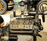
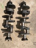
The front motor mounts bolted to brackets on either side of the timing cover. Interestingly these bolt holes were still drilled and tapped on all other American built flatheads. They continued to be used through 1936 for motor mounts, then they were not used again until 1953 trucks! The front of the block in 1932 was flat between the water inlets and the timing cover. The crankshaft were forged in 1932, the only 221-239-255 cranks to be forged, and they featured a very short snout. The snout was just long enough to hold the timing gear, crank pulley, and its retaining nut. This short crank snout was continued to the end of 1938 engine production. The 1932 motor mounts, flat block, and short crank can be seen in this picture:
1932 V8 engines did not use cam bearings. Camshafts ran right in the cast iron. I do not know if there is enough material in the block to cut for conventional cam bearings. 1932 was also the only year Ford used a forged camshaft in the flathead V8s. Racers used to search for these camshafts to regrind for racing camshafts.
I have not covered the rest of the 1932 one-year-only engine parts as this comprises almost the whole engine. If I ever get around to doing similar discussions on intakes, water pumps, distributors, etc, I will try to cover each in their respective story.
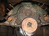
By the beginning of 1933 production, Ford had developed the V8 engine to the point that it was no longer a prototype motor being tested by the public. 1933 also continued the quest for more performance. The heads were changed to aluminum for passenger car use and the compression ratio was raised. The advance curve in the distributor was changed on the passenger car engines with aluminum heads to allow 22 total degrees instead of 18, 4 crankshaft degrees more advance. The advance curve change was a one year deal as Ford reverted back to 18 total in 1934 and stayed with 18 degrees total through the end of the front mount distributors. The front motor mounts were relocated to the water inlets, and the oil pan was made out of stamped steel. The front of the block between the water inlets and the timing cover had a recess added early in the 1933 production run to save some iron. This recess is featured on all flathead V8s from 1933 on. Crankshafts were now cast rather than forged, though some of the forged cranks continued to find their way into engines through 1934. The blocks still did not use cam bearings. The water petcocks are angled out instead of straight down. Some early Canadian blocks had casting to allow the block to be machined for either straight down or angled petcocks. The pictures of 1933 blocks are provided by David J. These are 3 1/16 bore, 21 stud blocks.
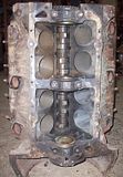
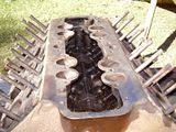
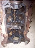
The recesses between the water inlets can be seen on the front of the block in this picture. The recesses in the 1933 blocks are the same depth on both sides of the timing cover. This engine has a forged crankshaft. The engine was upside down when this picture was taken and I flipped the picture over.
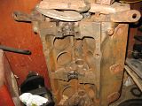
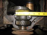
This is the crankcase area of a 1933 block. Note the four freeze plugs in the oil pan rail and the area to the passenger side of the front main bearing as it lacks the opening for crankcase ventilation. The distance between the studs on the main caps will measure approximately 3 inches center to center, common to all poured bearing Ford V8 blocks.
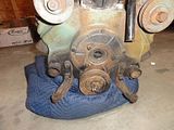
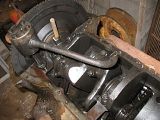
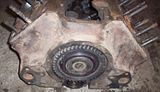
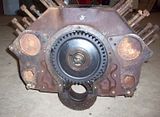
Here is the oil pump, rear main, and flywheel of the 1933 motor with the forged crankshaft.
The fuel pump push rod area of the non-ventilated blocks looks like this.

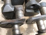
David J also provided pictures of both a forged crankshaft and a cast crankshaft. The forged crankshaft has a constant width #2 counterweight while the cast crankshaft has an extra bit of weight cast in that makes the counterweight thicker on the outer part, among other differences. The differences can be seen in these pictures. The forged crankshaft is on the left and cast crankshaft is on the right.
Here is a closer look at the rear of the crankshafts. Again, the forged is on the left.
1934 featured an exciting upgrade for the Ford V8, the world's first 180 intake manifold. As far as the engine block is concerned, 1934 was the same as 1933.
1935 engines finally got crankcase ventilation. This was added as a triangular vent in the front of the block, next to the front main bearing. With the addition of the vent in the passenger side of the block, the recess between the timing cover and the water inlet on that side of the block was made shallower. The oil pan was modified to work with this vent area and has a funny little triangular protrusion with a slot in the back. 1935 blocks also started using cam bearings. These are 3 1/16 bore, 21 stud blocks.
Here is the crankcase area. Notice the crankcase ventilation hole next to the front main bearing.
Here is the front of the block. Notice the depressions between the water inlets on each side of the timing cover. It is hard to see in this picture, but the passenger side depression is shallower than the driver side depression.
Another change to come with the crankcase ventilation was a cast in baffle in the fuel pump push rod area of the valley, as can be seen in this picture.
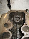
The noteworthy feature in this picture is the crankcase breather tube.
Late in 1935 Ford introduced V8 engines with insert main bearings. This is the block that is known as the 36 LB. Ford kept producing poured bearing blocks along side the insert bearing blocks during 1936 production. There is sometime an LB stamped on the passenger side intake rail near the front of the block, indicating an insert bearing motor. I have seen insert bearing motors without this marking. I also suspect that at least one motor has had someone add this in a dis-honest attempt to get more money for a motor. The main bearings were enlarged to 2.400 inches on the insert bearing blocks and the main cap studs were moved apart to make room for the bigger bearings. The distance between the main cap studs on an insert block is approximately 3 ¼ inches. The oil pan was modified to fit over the larger main caps. These are 3 1/16 bore, 21 stud blocks.
Here is the front of an insert motor. Notice how the exterior features are identical to the poured motor.

I have been told that Canadian blocks of this era feature this hole.
1937 and later Ford V8 engines were all insert main motors. The water pumps were moved from the heads to the front of the block. This was done to improve cooling. The water outlet was moved to the center of each head. Early 1937 passenger car engines had aluminum heads, while most production used cast iron heads. Ford make block off plates to cover the water pump mounts on these blocks to allow 1932 through 1936 heads to be used on these motors. These are 3 1/16 bore 21 stud blocks.
Here is the water pump mounting area on the front of the block.
The crankcase area was mostly unchanged from the earlier insert bearing motors. The main bearing size remained 2.400 inches.
The cylinder head deck is pretty much identical to the earlier 21 stud blocks.

In 1938 is when the story starts to get confusing again. Early 1938 Fords continued with the 21 stud motor from 1937. At the same time Ford started casting blocks with 24 studs per cylinder head, and these motors started filtering into production. The later in the production run a 1938 Ford is, the more likely it is to have a 24 stud motor. The crankshaft, main bearings, accessories, in fact everything else but the block and heads, was the same between 21 and 24 stud motors in 1938. Why then did Ford bother? The answer comes in 1939. These are 221 cubic inch engines, either 21 or 24 stud.
Here is a picture of a 1938 24 stud motor. The cylinder heads are one year only, featuring a cast in part number on the face of the heads. The battery cable is not supposed to attach to the middle head stud.