The electric fuel gauge has a coil that heats up with amperage from the tank sender which also has variable output controlled by arm position which heats a bi-metal strip sending amps to the gauge.
From
https://forums.aaca.org/topic/238627...-gauge-repair/
"
19tom40 Posted June 30, 2014
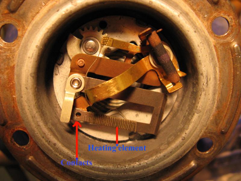
A good original type sending unit should read near 0 ohms at all positions of the arm. An ohm meter will read the resistance of the coil wound around the bi-metal strip and the resistance of the contact points. The coil only has a few windings and will have very little resistance. The dash unit has no control over the amount that the needle moves, this is done by the sending unit. As the amount of fuel shown by the dash gauge is just an approximate value, the full current test is accurate in determining if the gauge is functional.
Here is a photo of the inside of an original type fuel sending unit. The gap in the contact points is controlled by the position of the float arm. If you do not have an original type available to you, remove the tank unit and connect it to the gauge with a jumper wire. Measure the depth of the tank and bend the arm on the sending unit to travel that distance. I like to have about 1.5" straight section near the part that moves the resister slider and then a 90 degree bend that is adjusted for the depth of the tank. Check to see that it reads full near the top and empty near the bottom. I don't have a photo of one at this time.
 "
"
Koates may chip in here.
Glenn